


- 5 -
3. ERROR CODES
3.1. Error E7
Incorrect power connection
Incorrect supply voltage: ……V Wrong coil for the cooking zone: FL RL RR FR
NO
YES
Cooking zone coil connected incorrectly: FL RL RR FR Cooking zone sensor connected incorrectly: FL RL RR FR
Damaged IGBT: 1 2 3 4
Damaged varistor No connection of filter PCB with the module
Replaced induction coil Replaced induction module
NO
YES
NO
YES
N
O
YES
YES
N
O
YES
N
O
N
O
YES
YES
N
O
N
O
YES
Are correct coils used?
Check whether the E7 error is indicated when
left or right cooking zones are activated (note
the result). Point 5.2.
Check the connection and the voltage on L1 and L2 power
conductors. Point 5.1.
Technician should note all defects found in the following
list:
Are the connections and
voltage correct?
Inform the client of an incorrect
cooking zone connection or
overvoltage — note the
recommendations according to
the service procedure
Check if the correct type induction coils are
used. Point 7
Is the E7 error
indicated when you
turn on the same
cooking zones?
Replace the induction module while paying
special attention to the correct connection of
induction coils and temperature sensors
Replace with correct coils.
Check the connection of cooking zone
induction coils and temperature sensors.
Point 10.5.
Is the connection
correct?
Check if the four IGBTs are operational. Point
8
Check if varistors are operational Point 10.6.
Are IGBTs
operational?
Replace the induction module while paying
special attention to the correct connection of
induction coils and temperature sensors
Check the connection between filter PCB and
induction module PCB. Point 10.1.
Swap the induction coils. Point 12
Check if the E7 error is
indicated.
Check if the E7 error is indicated. Point 5.2.
Check the correct operation of the hob Point
9.2.
Replace the induction coils on the side which
indicates the E7 error
Damage to the varistor is due to
the miswiring of power
conductors or electrical network
overvoltage. - Add the
recommendations consistent with
the service procedure
Check the correct operation of the hob Point
9.2.
Is the connection
correct?
Assemble the hob paying special attention to
the correct connection of induction coils and
temperature sensors
Replace the induction module while paying
special attention to the correct connection of
induction coils and temperature sensors
Check whether the E7 error is indicated when
left or right cooking zones are activated.
Point 6.1.
Are varistors
operational?
Check the correct operation of
the hob Point 9.2.
Check the correct operation of the hob Point
9.2.
Check the correct operation of the hob Point
9.2.
Does the hob operate
correctly?
Replace the induction module while paying
special attention to the correct connection of
induction coils and temperature sensors
End of repair
Compare whether the E7 error is indicated
when you turn on the same cooking zones
(left or right) as before the coils are swapped.
Содержание 4VI515 Series
Страница 3: ... 3 1 HOB FEATURES AND COMPONENTS ...
Страница 13: ... 13 2 single coils 6 dual coils 5 single coils ...
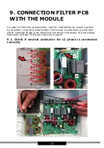
Страница 18: ... 18 9 2 Check if neutral conductor for L1 phase is connected correctly ...
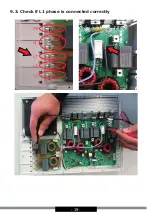
Страница 19: ... 19 9 3 Check if L1 phase is connected correctly ...
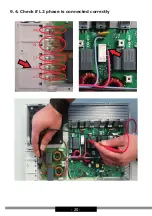
Страница 20: ... 20 9 4 Check if L2 phase is connected correctly ...
Страница 21: ... 21 9 5 Check if coils are connected correctly ...
Страница 28: ...serwis dokumentacja amica com pl ...


