background image

CyberResearch

® 

CPU Cards 


CZGL AT-16 


CyberResearch, Inc

.  

157


25 Business Park Drive 

P: (203) 643-5000; F: (203) 643-5001 

Branford, CT USA 

www.cyberresearch.com 

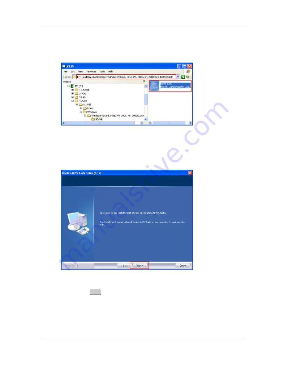
Step 3: 

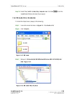
Browse to “

E:\4-Audio\ALC665\Windows\Windows 98Gold, 98se, Me, 2000, 

XP, 2003(32,64 bits)\A3.84

” 

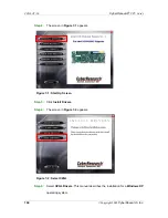
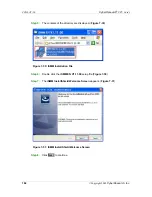
Figure 7-21


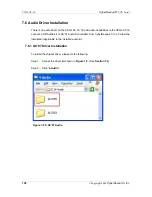
Figure 7-21: AC’97 Audio Driver Options 

Step 4: 

Double-click the installation file in 

Figure 7-21

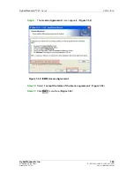
Step 5: 

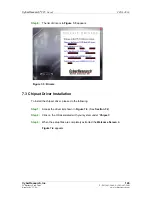
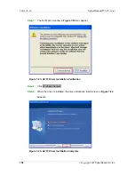
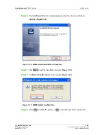
The AC’97 Driver Installation screen in 

Figure 7-22

 appears. 


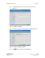
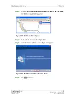
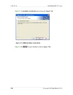
Figure 7-22: AC’97 Driver Installation Welcome Screen 

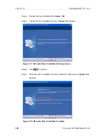
Step 6: 

Click 

N

EXT

 to continue. 

Содержание CZGL AT-16

Страница 1: ...y be reproduced without permission CZGL AT 16 PISA Single Board Computer with 1 6GHz Atom CPU VGA LAN SATA USB Audio and CompactFlash Socket CyberResearch Inc www cyberresearch com 25 Business Park Dr...

Страница 2: ......

Страница 3: ...Research and CZGL AT 16 are trademarks of CyberResearch Inc Other product names mentioned herein are used for identification purposes only and may be trademarks and or registered trademarks of their r...

Страница 4: ...Research CPU Cards iv Copyright 2009 CyberResearch Inc Revision History Revision Description Date of Issue 1 0 Initial Release November 21st 2008 2 0C Revision June 17 2009 2 1C Removed references to...

Страница 5: ...below WARNING This is an example of a warning message Failure to adhere to warning messages may result in permanent damage to the CZGL AT 16 or personal injury to the user Please take warning message...

Страница 6: ...ns or instructions contained therein can help avoid making mistakes Notes are easy to recognize The word note is written as NOTE both capitalized and bold and is followed by text The text is the cauti...

Страница 7: ...w are missing please do not proceed with the installation Contact a CyberResearch sales representative by calling 203 643 5000 or by sending an email to www cyberresearch com The items listed below sh...

Страница 8: ...0 2 2 DATA FLOW 11 2 3 INTEL ATOM PROCESSOR 12 2 3 1 Overview 12 2 3 2 Features 12 2 3 3 Front Side Bus FSB 13 2 4 INTEL 945GSE NORTHBRIDGE CHIP 13 2 4 1 DDR2 Controller 13 2 4 2 Graphics 14 2 4 2 1 A...

Страница 9: ...bit Ethernet Connector 22 2 5 9 SPI Bus Components 23 2 5 9 1 SPI BIOS 23 2 6 ENVIRONMENTAL AND POWER SPECIFICATIONS 24 2 6 1 System Monitoring 24 2 6 2 Operating Temperature and Temperature Control 2...

Страница 10: ...ATA Drive Connectors 50 4 2 16 Parallel Port Connector 51 4 2 17 Serial Port Connector RS 232 52 4 2 18 Serial Port Connector RS 232 422 485 53 4 2 19 SDVO Connector 54 4 2 20 TV Out Connector 55 4 2...

Страница 11: ...ion 78 5 8 4 Dual RS 232 Cable with Slot Bracket 79 5 8 5 Floppy Drive Cable Connection 80 5 8 6 Parallel Port Cable without Bracket 81 5 8 7 SATA Drive Connection 82 5 8 8 USB Cable Dual Port with Sl...

Страница 12: ...5 5 Removable Drives 130 6 6 SECURITY 132 6 7 CHIPSET 133 6 7 1 Northbridge Chipset Configuration 134 6 7 1 1 Video Function Configuration 136 6 7 2 Southbridge Configuration 138 6 8 EXIT 140 7 SOFTW...

Страница 13: ...CT USA www cyberresearch com C 2 DIO CONNECTOR PINOUTS 177 C 3 ASSEMBLY LANGUAGE SAMPLES 178 C 3 1 Enable the DIO Input Function 178 C 3 2 Enable the DIO Output Function 178 D WATCHDOG TIMER 179 E AD...

Страница 14: ...nector Location 9 pin 36 Figure 4 5 LCD Backlight Connector Pinout Locations 37 Figure 4 6 Battery Connector Location 38 Figure 4 7 BIOS Programming Connector Pinouts 39 Figure 4 8 CF Card Socket Loca...

Страница 15: ...LPT Cable Connection 82 Figure 5 10 SATA Drive Cable Connection 83 Figure 5 11 SATA Power Drive Connection 84 Figure 5 12 Dual USB Cable Connection 85 Figure 5 13 Connect the LPT Device 86 Figure 5 1...

Страница 16: ...97 Driver Installation Verification 158 Figure 7 24 AC 97 Driver Installation Complete 158 Figure 7 25 HD Audio 159 Figure 7 26 HD Audio Driver Options 159 Figure 7 27 HD Audio Driver Installation Wel...

Страница 17: ...Pinouts 38 Table 4 7 BIOS Programming Connector 39 Table 4 8 CF Card Socket Pinouts 41 Table 4 9 DIO Connector Pinouts 42 Table 4 10 CPU Fan Connector Pinouts 42 Table 4 11 Floppy Disk Connector Pinou...

Страница 18: ...2 AT ATX Power Selection Jumper Settings 70 Table 5 3 Clear CMOS Jumper Settings 70 Table 5 4 CF Card Setup Jumper Settings 71 Table 5 5 COM2 RS 232 422 485 Selection Jumper Pinouts 71 Table 5 6 LCD...

Страница 19: ...9 Power Configuration 112 BIOS Menu 10 ACPI Configuration 113 BIOS Menu 11 Advanced Power Management Configuration 114 BIOS Menu 12 Remote Access Configuration 117 BIOS Menu 13 USB Configuration 121...

Страница 20: ......

Страница 21: ...CyberResearch CPU Cards CZGL AT 16 CyberResearch Inc 1 25 Business Park Drive P 203 643 5000 F 203 643 5001 Branford CT USA www cyberresearch com Chapter 1 1 Introduction...

Страница 22: ...bles which provide a single cable connection on a card slot and a cable splitting the signal into the component parts Finally an SDVO connector provides a direct connection from the Northbridge SDVO p...

Страница 23: ...03 643 5000 F 203 643 5001 Branford CT USA www cyberresearch com 1 2 Overview Photo The CZGL AT 16 has a wide variety of peripheral interface connectors 746HFigure 1 2 is a labeled photo of the periph...

Страница 24: ...ectors on board 1 x ATX power control connector 1 x Audio kit connector 1 x Backlight inverter connector 1 x Battery connector 1 x BIOS programming header 1 x CompactFlash slot 1 x Digital I O connect...

Страница 25: ...l interface connectors on the board rear panel 2 x Network ports 2 x USB ports 1 x VGA port The CZGL AT 16 has the following on board jumpers ATX power control Clear CMOS COM2 port mode CompactFlash c...

Страница 26: ...ort One RS 232 422 485 serial port USB2 0 Six USB 2 0 devices supported four internal two external Hard Drives One 40 pin IDE connector SATA Two 1 5 Gb s SATA drives supported Keyboard mouse Internal...

Страница 27: ...16 CyberResearch Inc 7 25 Business Park Drive P 203 643 5000 F 203 643 5001 Branford CT USA www cyberresearch com Specification CZGL AT 16 Dimensions LxH 185 mm x 127 6 mm Weight GW NW 1000 g 252 g Ta...

Страница 28: ...CZGL AT 16 CyberResearch CPU Cards 8 Copyright 2009 CyberResearch Inc Chapter 2 2 Detailed Specifications...

Страница 29: ...h Inc 9 25 Business Park Drive P 203 643 5000 F 203 643 5001 Branford CT USA www cyberresearch com 2 1 Dimensions 2 1 1 Board Dimensions The dimensions of the board are listed below Length 185 mm Heig...

Страница 30: ...CPU Cards 10 Copyright 2009 CyberResearch Inc 2 1 2 External Interface Panel Dimensions External peripheral interface connector panel dimensions are shown in 748HFigure 2 2 Figure 2 2 External Interf...

Страница 31: ...3 643 5000 F 203 643 5001 Branford CT USA www cyberresearch com 2 2 Data Flow Figure 2 3 shows the data flow between the two on board chipsets and other components installed on the motherboard and des...

Страница 32: ...The processor supports a 533 MHz FSB and has a 512 KB L2 cache The low power processor has a maximum power of 2 5 W The CPU is shown in Figure 2 4 below Figure 2 4 CPU and Northbridge Connections 2 3...

Страница 33: ...peedStep Technology Execute Disable Bit support for enhanced security 2 3 3 Front Side Bus FSB The Intel Atom processor on the CZGL AT 16 is interfaced to the Intel 945GSE Northbridge through a 533 MH...

Страница 34: ...graphics engine with an integrated 400 MHz RAMDAC and hot plug CRT support supports analog CRT monitors up to QXGA 2 4 2 2 LVDS A 30 pin LVDS crimp connector is interfaced to the Intel 945GSE graphics...

Страница 35: ...irectly to the SDVO output on the Intel 945GSE The SDVO connector is connected to an SDVO graphics card Concurrent operation of PCIe x 1 with SDVO Two SDVO ports supported o SDVO is muxed onto the PCI...

Страница 36: ...s Base Specification Revision 1 0a Complies with PCI Local Bus Specification Revision 2 3 and supports 33 MHz PCI operations Supports ACPI Power Management Logic Contains o Enhanced DMA controller o I...

Страница 37: ...Count LPC interface Supports Firmware Hub FWH interface Serial peripheral interface support 2 5 1 HD Audio Controller The audio connector on the CZGL AT 16 is connected to the HD Audio AC 97 audio ch...

Страница 38: ...33 IDE devices 2 2 2 PIO Mode 0 4 0 4 0 4 PIO Max Transfer Rate 16 6 MB s 16 6 MB s 16 6 MB s DMA UDMA designation UDMA 5 UDMA 4 UDMA 2 DMA UDMA Max Transfer 100 MB s 66 MB s 33 MB s Controller Interf...

Страница 39: ...full speed or low speed USB devices are supported by the Intel ICH7M on the CZGL AT 16 High speed USB 2 0 with data transfers of up to 480 MB s is enabled with the Intel ICH7M integrated Enhanced Hos...

Страница 40: ...EEE 1284 Parallel Port Keyboard Controller Watchdog Timer Some of the Super I O features are described in more detail below 2 5 6 1 LPC Interface The LPC interface on the Super I O complies with the I...

Страница 41: ...tor is reserved for fan speed detection and interfaced to the fan speed controller on the Super I O The fan speed is then reported in the BIOS 2 5 6 6 Keyboard Mouse Controller The Super I O keyboard...

Страница 42: ...5 8 1 Gigabit Ethernet Connector Two of the four PCIe lanes on the Intel ICH7M PCIe lanes are connected to the Realtek RTL8111CP PCIe GbE controllers The Realtek RTL8111CP PCIe GbE controllers combin...

Страница 43: ...802 3 IEEE 802 3u IEEE 802 3ab Supports IEEE 802 1P Layer 2 Priority Encoding Supports IEEE 802 1Q VLAN tagging Serial EEPROM Transmit Receive on chip buffer support Supports power down link down powe...

Страница 44: ...monitors the following fan speeds CPU Fan speed Voltage inputs on the CZGL AT 16 Super I O Enhanced Hardware Monitor monitors the following voltages CPU Core 1 05 V 3 30 V 5 00 V 12 V 1 5 V 1 8 V 5 V...

Страница 45: ...eared on the lower side of the heat sink before it is mounted on the CPU Heat sinks are also mounted on the Northbridge and Southbridge chipsets to ensure the operating temperature of these chips rema...

Страница 46: ...CZGL AT 16 CyberResearch CPU Cards 26 Copyright 2009 CyberResearch Inc Chapter 3 3 Unpacking...

Страница 47: ...an anti static wristband Wearing a simple anti static wristband can help to prevent ESD from damaging the board Self grounding Before handling the board touch any grounded conducting material During...

Страница 48: ...se do not proceed with the installation Contact a CyberResearch sales representative by calling 203 643 5000 or by sending an email to www cyberresearch com 3 3 1 Package Contents The CZGL AT 16 is sh...

Страница 49: ...esearch com Quantity Item and Part Number Image Table 3 1 Packing List 3 3 2 Optional Items The CZGL AT 16 is shipped with the following components Item and Part Number Image 5 1 Channel AC 97 audio k...

Страница 50: ...CZGL AT 16 CyberResearch CPU Cards 30 Copyright 2009 CyberResearch Inc Item and Part Number Image IDE cable SATA power cable Table 3 2 Power Consumption...

Страница 51: ...CyberResearch CPU Cards CZGL AT 16 CyberResearch Inc 31 25 Business Park Drive P 203 643 5000 F 203 643 5001 Branford CT USA www cyberresearch com Chapter 4 4 Connectors...

Страница 52: ...heral Interface Connectors This chapter outlines all internal and external connectors on the CZGL AT 16 4 1 1 Layout 768HFigure 4 1 shows the on board peripheral connectors rear panel peripheral conne...

Страница 53: ...ral Interface Connectors 769HTable 4 1 shows a list of the peripheral interface connectors on the CZGL AT 16 Detailed descriptions of these connectors can be found below Connector Type Label ATX power...

Страница 54: ...LPT1 RS 232 connector 10 pin header COM1 RS 232 422 485 connector 14 pin header COM2 SATA connector SATA port SATA1 SATA2 SDVO connector Flat cable connector SDVO1 TV connector 6 pin header TV1 USB co...

Страница 55: ...ll the internal peripheral connectors on the CZGL AT 16 4 2 1 ATX Power Control Connector CN Label ATXCTL1 CN Type 3 pin wafer 1x3 CN Location See Figure 4 3 CN Pinouts See Table 4 3 The ATX power sup...

Страница 56: ..._AUDIO1 CN Type 9 pin header 2x5 CN Location See Figure 4 4 CN Pinouts See Table 4 4 The 9 pin audio connector is connected to external audio devices including speakers and microphones for the input a...

Страница 57: ...9 pin 4 2 3 Backlight Inverter Connector CN Label INVERTER1 CN Type 5 pin box header 1x5 CN Location See Figure 4 5 CN Pinouts See Table 4 5 The backlight inverter connector provides the backlight on...

Страница 58: ...is connected to a backup battery The battery connector is also used to reset the CMOS memory if the incorrect BIOS settings have been made and the system cannot boot up Figure 4 6 Battery Connector Lo...

Страница 59: ...sed for the BIOS Figure 4 7 BIOS Programming Connector Pinouts PIN DESCRIPTION PIN DESCRIPTION 1 3 3 V 2 GND 3 CS 4 CLOCK 5 SO 6 SI 7 N C 8 N C Table 4 7 BIOS Programming Connector 4 2 6 CompactFlash...

Страница 60: ...TA 3 27 DATA 11 3 DATA 4 28 DATA 12 4 DATA 5 29 DATA 13 5 DATA 6 30 DATA 14 6 DATA 7 31 DATA 15 7 CE 32 CE2 8 A10 33 VS1 9 OE 34 IOR 10 A9 35 IOW 11 A8 36 WE 12 A7 37 IRQ 13 VCC1 38 VCC2 14 A6 39 CSEL...

Страница 61: ...Card Socket Pinouts 4 2 7 Digital I O Connector CN Label DIO1 CN Type 10 pin header 2x5 CN Location See Figure 4 9 CN Pinouts See Table 4 9 The digital input output connector is managed through a Supe...

Страница 62: ...7HFigure 4 10 CN Pinouts See 778HTable 4 10 The cooling fan connector provides a 12 V 500mA current to the cooling fan The connector has a rotation pin to get rotation signals from fans and notify the...

Страница 63: ...e 34 pin header 2x17 CN Location See Figure 4 11 CN Pinouts See Table 4 11 The floppy disk connector is connected to a floppy disk drive Figure 4 11 Floppy Disk Connector Location PIN NO DESCRIPTION P...

Страница 64: ...D 30 READ DATA 31 GND 32 SIDE 1 SELECT 33 GND 34 DISK CHANGE Table 4 11 Floppy Disk Connector Pinouts 4 2 10 Front Panel Connector CN Label F_PANEL1 CN Type 8 pin header 2x4 CN Location See Figure 4 1...

Страница 65: ...CRIPTION FUNCTION PIN DESCRIPTION Power button 1 PWR_BTN Power LED 2 PWR_LED 3 PWR_BTN 4 PWR_LED HDD LED 5 HDD_LED Reset button 6 RESET 7 HDD_LED 8 RESET Table 4 12 Front Panel Connector Pinouts 4 2 1...

Страница 66: ...UND 3 DATA 7 4 DATA 8 5 DATA 6 6 DATA 9 7 DATA 5 8 DATA 10 9 DATA 4 10 DATA 11 11 DATA 3 12 DATA 12 13 DATA 2 14 DATA 13 15 DATA 1 16 DATA 14 17 DATA 0 18 DATA 15 19 GROUND 20 N C 21 IDE DRQ 22 GROUND...

Страница 67: ...13 IDE Connector Pinouts 4 2 12 Infrared Interface Connector CN Label IR1 CN Type 5 pin header 1x5 CN Location See 787HFigure 4 14 CN Pinouts See 788HTable 4 14 The infrared interface connector suppo...

Страница 68: ...See Table 4 15 The keyboard and mouse connector can be connected to a standard PS 2 cable or PS 2 Y cable to add keyboard and mouse functionality to the system Figure 4 15 Keyboard Mouse Connector Lo...

Страница 69: ...an be connected to single channel or dual channel 18 bit or 36 bit LVDS panel Figure 4 16 LVDS LCD Connector Pinout Locations PIN NO DESCRIPTION PIN NO DESCRIPTION 1 GROUND 2 GROUND 3 LVDSA_Y0 4 LVDSA...

Страница 70: ...Drive Connectors CN Label SATA1 SATA2 CN Type 7 pin SATA drive connectors CN Location See 793HFigure 4 17 CN Pinouts See 794HTable 4 17 The four SATA drive connectors are each connected to a first ge...

Страница 71: ...ctor CN Label LPT1 CN Type 26 pin header 2x13 CN Location See Figure 4 18 CN Pinouts See Table 4 18 The 26 pin parallel port connector connects to a parallel port connector interface or some other par...

Страница 72: ...t Connector Pinouts 4 2 17 Serial Port Connector RS 232 CN Label COM1 CN Type 10 pin header 2x5 CN Location See 795HFigure 4 19 CN Pinouts See 796HTable 4 19 The 10 pin serial port connector provides...

Страница 73: ...x7 CN Location See Figure 4 20 CN Pinouts See 796HTable 4 20 The serial port connector provides an RS 232 RS 422 or RS 485 communications channel Figure 4 20 RS 232 422 485 Connector Pinout Locations...

Страница 74: ...or connects to an SDVO video card available from CyberResearch Inc The SDVO connector interfaces directly to the SDVO port on the Intel ICH7M Figure 4 21 SDVO Connector Pinout Locations PIN NO DESCRIP...

Страница 75: ...2 SDVO1_STALL 33 SDVO1_STALL 34 GND 35 SDVO_TVCLKIN 36 SDVO_TCCLKIN 37 GND 38 SDVO_CLK 39 SDVO_DATA 40 PCIRST 41 5 VS 42 5 VS 43 5 VS 44 N C 45 N C 46 GND 47 GND Table 4 21 SDVO Connector Pinouts 4 2...

Страница 76: ...signal 5 GND 6 ABLUE_CVBS Table 4 22 TV Port Connector Pinouts 4 2 21 USB Connectors CN Label USB01 USB23 CN Type 8 pin header 2x4 CN Location See 801HFigure 4 23 CN Pinouts See 802HTable 4 23 The 2x4...

Страница 77: ...PTION PIN NO DESCRIPTION USB Connector 1 USB Connector 2 1 VCC 2 GND 3 DATA1 4 DATA2 5 DATA1 6 DATA2 7 GND 8 VCC Table 4 23 USB Port Connector Pinouts 4 3 External Peripheral Interface Connector Panel...

Страница 78: ...ee 809HTable 4 24 The CZGL AT 16 is equipped with two built in RJ 45 Ethernet controllers The controllers can connect to the LAN through two RJ 45 LAN connectors There are two LEDs on the connector in...

Страница 79: ...ity YELLOW Linked Table 4 25 LAN Connector LEDs 4 3 2 USB Connectors CN Label USB_C4 and USB_C5 CN Type USB port CN Location See 814HFigure 4 24 CN Pinouts See 815HTable 4 26 The CZGL AT 16 has two ex...

Страница 80: ...Copyright 2009 CyberResearch Inc Figure 4 26 VGA Connector PIN DESCRIPTION PIN DESCRIPTION 1 RED 2 GREEN 3 BLUE 4 NC 5 GND 6 CRT_PLUG 7 GND 8 GND 9 VCC 10 GND 11 NC 12 DDC DAT 13 HSYNC 14 VSYNC 15 DD...

Страница 81: ...CyberResearch CPU Cards CZGL AT 16 CyberResearch Inc 61 25 Business Park Drive P 203 643 5000 F 203 643 5001 Branford CT USA www cyberresearch com Chapter 5 5 Installation...

Страница 82: ...ZGL AT 16 or any other electrical component is handled the following anti static precautions are strictly adhered to Wear an anti static wristband Wearing a simple anti static wristband can help to pr...

Страница 83: ...manual should be carefully followed in order to prevent damage to the CZGL AT 16 CZGL AT 16 components and injury to the user Before and during the installation please DO the following Read the user m...

Страница 84: ...ng list are present A compatible memory module is properly inserted into the slot The CF Type I or CF Type II card is properly installed into the CF socket The jumpers have been properly configured Th...

Страница 85: ...rds and CF Type II cards For the complete specifications of the supported CF cards please refer to Chapter 2 To install the a CF card Type 1 or Type 2 onto the CZGL AT 16 please follow the steps below...

Страница 86: ...nector is required when using an ATX power source To setup the CZGL AT 16 for ATX power follow the steps below Step 1 Set the ATX jumpers there are two as shown in AT ATX Power Selection in Section 5...

Страница 87: ...siness Park Drive P 203 643 5000 F 203 643 5001 Branford CT USA www cyberresearch com Figure 5 2 ATX Power Control Connector Step 3 Turn on with the front panel connector The system is turned on using...

Страница 88: ...tic clip and to OPEN a jumper means removing the plastic clip from a jumper Jumper Locations Before the CZGL AT 16 is installed in the system the jumpers must be set in accordance with the desired con...

Страница 89: ...com Figure 5 3 Jumper Location 5 6 1 AT ATX Power Selection Jumper Label ATXCTL1 and J_AUTOPWR1 Jumper Type 3 pin wafer and 2 pin header Jumper Settings See Table 5 2 Jumper Location See Figure 5 3 Th...

Страница 90: ...stem BIOS information To do this use the jumper cap to close pins 2 and 3 for a few seconds then reinstall the jumper clip back to pins 1 and 2 If the CMOS Settings Wrong message is displayed during t...

Страница 91: ...Card Setup jumper settings are shown in Table 5 4 CF Card Setup Description Open Slave Closed Master Table 5 4 CF Card Setup Jumper Settings 5 6 4 COM2 RS 232 422 485 Selection Jumper Jumper Label JP...

Страница 92: ...l Selection Description Open 640 x 480 18 bit 1 2 800 x 480 18 bit 3 4 800 x 600 18 bit 1 2 and 3 4 1024 x 768 18 bit 5 6 1280 x 1024 36 bit 1 2 and 5 6 1400 x 1050 36 bit 3 5 and 5 6 1400 x 900 36 bi...

Страница 93: ...3 V 2 3 5 V Table 5 7 LVDS Voltage Selection Jumper Settings 5 7 Chassis Installation 5 7 1 Airflow WARNING Airflow is critical to the cooling of the CPU and other onboard components The chassis in w...

Страница 94: ...d Installation To install the CZGL AT 16 motherboard into the chassis please refer to the reference material that came with the chassis 5 8 Internal Peripheral Device Connections The cables listed in...

Страница 95: ...jacks One audio jack Mic In connects to a microphone The remaining two audio jacks Line In and Line Out connect to two speakers To install the audio kit please refer to the steps below Step 1 Connect...

Страница 96: ...udio jack one speaker to the line out audio jack and a microphone to the mic in audio jack Step 6 Install the driver If the 5 1 channel audio kit is used the ALC655 Realtek codec driver must be instal...

Страница 97: ...the audio kit cable The audio kit is shipped with a cable that connects the audio kit to the CZGL AT 16 Connect the cable to the connector on the back of the audio kit Make sure the pins are properly...

Страница 98: ...r installation instructions Step 0 Step 1 corresponds to pin 1 on the connector Step 0 5 8 3 ATA Flat Cable Connection The ATA 66 100 flat cable connects to the CZGL AT 16 to one or two IDE devices To...

Страница 99: ...8 4 Dual RS 232 Cable with Slot Bracket The dual RS 232 cable slot connector consists of two connectors attached to two independent cables Each cable is then attached to a D sub 9 male connector that...

Страница 100: ...that came with the chassis Step 0 5 8 5 Floppy Drive Cable Connection The FDD flat cable connects to the CZGL AT 16 to one FDD device To connect an FDD to the CZGL AT 16 please follow the instructions...

Страница 101: ...Cable without Bracket The optional parallel port LPT cable respectively connects the on board LPT 26 pin box header to an external LPT device like a printer The cable comprises a 26 pin female header...

Страница 102: ...LPT interface connector to the chassis please refer to the installation instructions that came with the chassis Step 5 Connect LPT device Once the LPT interface connector is connected to the chassis...

Страница 103: ...e SATA cable and insert the cable connector into the onboard SATA drive connector See 852HFigure 5 10 Figure 5 10 SATA Drive Cable Connection Step 3 Connect the cable to the SATA disk Connect the conn...

Страница 104: ...the connectors The locations of the USB connectors are shown in Chapter 3 WARNING If the USB pins are not properly aligned the USB device can burn out Step 2 Align the connectors The cable has two con...

Страница 105: ...203 643 5001 Branford CT USA www cyberresearch com Figure 5 12 Dual USB Cable Connection Step 4 Attach the bracket to the chassis The USB 2 0 connectors are attached to a bracket To secure the bracket...

Страница 106: ...evices VGA monitors To install these devices connect the corresponding cable connector from the actual device to the corresponding CZGL AT 16 external peripheral interface connector making sure the pi...

Страница 107: ...e RJ 45 connector Once aligned gently insert the LAN cable RJ 45 connector into the onboard RJ 45 connector Step 0 5 9 2 USB Device Connection Single Connector There are two external USB 2 0 connector...

Страница 108: ...as a single female DB 15 connector on the external peripheral interface panel The DB 15 connector is connected to a CRT or VGA monitor To connect a monitor to the CZGL AT 16 please follow the instruct...

Страница 109: ...ctor Once the connectors are properly aligned with the insert the male connector from the VGA screen into the female connector on the CZGL AT 16 See 863HFigure 5 16 Figure 5 16 VGA Connector Step 4 Se...

Страница 110: ...CZGL AT 16 CyberResearch CPU Cards 90 Copyright 2009 CyberResearch Inc Chapter 6 6 BIOS Setup...

Страница 111: ...Press the DELETE key when the Press Del to enter SETUP message appears on the screen If the message disappears before the DELETE key is pressed restart the computer and try again 6 1 2 Using Setup Us...

Страница 112: ...Reboot After Configuration Changes If the computer cannot boot after changes to the system configuration is made CMOS defaults Use the jumper described in Chapter 5 6 1 5 BIOS Menu Bar The menu bar o...

Страница 113: ...System Overview The System Overview lists a brief summary of different system components The fields in System Overview cannot be changed The items shown in the system overview include AMI BIOS Displa...

Страница 114: ...the system date Manually enter the day month and year 6 3 Advanced Use the Advanced menu 865HBIOS Menu 2 to configure the CPU and peripheral devices through the following sub menus WARNING Setting th...

Страница 115: ...CyberResearch CPU Cards CZGL AT 16 CyberResearch Inc 95 25 Business Park Drive P 203 643 5000 F 203 643 5001 Branford CT USA www cyberresearch com BIOS Menu 2 Advanced...

Страница 116: ...nd configure the CPU BIOS Menu 3 CPU Configuration The CPU Configuration menu 874HBIOS Menu 3 lists the following CPU details Manufacturer Lists the name of the CPU manufacturer Brand String Lists the...

Страница 117: ...t the configuration of the IDE devices installed in the system BIOS Menu 4 IDE Configuration ATA IDE Configurations Compatible Use the ATA IDE Configurations option to configure the ATA IDE controller...

Страница 118: ...nel PATA Only The IDE drives are enabled on the primary and secondary IDE channels SATA drives are disabled IDE Master and IDE Slave When entering setup BIOS auto detects the presence of IDE devices B...

Страница 119: ...IDE Slave Configuration Auto Detected Drive Parameters The grayed out items in the left frame are IDE disk drive parameters automatically detected from the firmware of the selected IDE disk drive The...

Страница 120: ...protocol is supported 32Bit Data Transfer Enables 32 bit data transfer Type Auto Use the Type BIOS option select the type of device the AMIBIOS attempts to boot from after the Power On Self Test POST...

Страница 121: ...lti sector transfers Disabled BIOS is prevented from using Multi Sector Transfer on the specified channel The data to and from the device occurs one sector at a time Auto DEFAULT BIOS auto detects Mul...

Страница 122: ...ned SWDMA0 Single Word DMA mode 0 selected with a maximum data transfer rate of 2 1 MB s SWDMA1 Single Word DMA mode 1 selected with a maximum data transfer rate of 4 2 MB s SWDMA2 Single Word DMA mod...

Страница 123: ...e it is required that an 80 conductor ATA cable is used S M A R T Auto Use the S M A R T option to auto detect disable or enable Self Monitoring Analysis and Reporting Technology SMART on the drive on...

Страница 124: ...e Floppy Configuration menu to configure the floppy disk drive connected to the system BIOS Menu 6 IDE Master and IDE Slave Configuration Floppy A B Use the Floppy A B option to configure the floppy d...

Страница 125: ...llers parallel ports and serial ports BIOS Menu 7 Super IO Configuration Parallel Port Address Disabled Use the Parallel Port Address option to select the parallel port base address Disabled DEFAULT N...

Страница 126: ...s in the extended capabilities port ECP mode The ECP mode supports bi directional communication between the system and the parallel port device and the transmission rates between the two are much fast...

Страница 127: ...transmitting and receiving mode Normal Default IrDA ASK IR Serial Port2 Address 2F8 IRQ3 Use the Serial Port2 Address option to select the I O and IRQ addresses Disabled No base address is assigned to...

Страница 128: ...OS Menu 8 Hardware Health Configuration CPU FAN Mode Setting Full On Mode Use the CPU FAN Mode Setting option to configure the second fan Full On Mode DEFAULT Fan is on all the time Automatic mode Fan...

Страница 129: ...gh temperature and therefore cause the system to be damaged The CPU Temp Limit of OFF option can only be set if the CPU FAN Mode Setting option is set to Automatic Mode Use the CPU Temp Limit of OFF o...

Страница 130: ...WM 070 The Fan 3 Start PWM option can only be set if the CPU FAN Mode Setting option is set to Automatic Mode Use the Fan 3 Start PWM option to select the PWM mode the fan starts to rotate with after...

Страница 131: ...rameters and values are shown The system parameters that are monitored are System Temperatures The following system temperatures are monitored o CPU Temperature o System Temperature Fan Speeds The CPU...

Страница 132: ...es the Advanced Configuration and Power Interface ACPI and Power Management APM options BIOS Menu 9 Power Configuration Select AT ATX Power ATX Power Use the Select AT ATX Power option to set the powe...

Страница 133: ...Menu 10 configures the Advanced Configuration and Power Interface ACPI and Power Management APM options BIOS Menu 10 ACPI Configuration Suspend Mode S1 POS Use the Suspend Mode option to specify the s...

Страница 134: ...nu 11 Advanced Power Management Configuration Restore on AC Power Loss Power On Use the Restore on AC Power Loss BIOS option to specify what state the system returns to if there is a sudden loss of po...

Страница 135: ...m is roused when the mouse is moved or a button on the keyboard is pressed Disabled DEFAULT Wake event not generated by activity on the keyboard or mouse Enabled Wake event generated by activity on th...

Страница 136: ...he Resume On RTC Alarm option to specify the time the system should be roused from a suspended state Disabled DEFAULT The real time clock RTC cannot generate a wake event Enabled If selected the follo...

Страница 137: ...enu BIOS Menu 12 to configure remote access parameters The Remote Access Configuration is an AMIBIOS feature and allows a remote host running a terminal program to display and configure the BIOS setti...

Страница 138: ...for remote access COM1 DEFAULT System is remotely accessed through COM1 COM2 System is remotely accessed through COM2 NOTE Make sure the selected COM port is enabled through the Super I O configuratio...

Страница 139: ...is set as the console redirection Software Software is set as the console redirection Redirection After BIOS POST Always Use the Redirection After BIOS POST option to specify when console redirection...

Страница 140: ...sed servers VT100 does not support all keys on the standard PC 101 key layout however The VT UTF8 convention makes available additional keys that are not provided by VT100 for the PC 101 keyboard Disa...

Страница 141: ...nu 13 to read USB configuration information and configure the USB settings BIOS Menu 13 USB Configuration USB Functions Enabled Use the USB Function option to enable or disable the USB controllers Dis...

Страница 142: ...trol the system even when there is no USB driver loaded onto the system Disabled Legacy USB support disabled Enabled DEFAULT Legacy USB support enabled Auto Legacy USB support disabled if no USB devic...

Страница 143: ...com BIOS Menu 14 PCI PnP Configuration IRQ Available Use the IRQ address to specify what IRQs can be assigned to a particular peripheral device Available DEFAULT The specified IRQ is available to be u...

Страница 144: ...specified DMA is reserved for use by Legacy ISA devices Available DMA Channels are DM Channel 0 DM Channel 1 DM Channel 3 DM Channel 5 DM Channel 6 DM Channel 7 Reserved Memory Size Disabled Use the...

Страница 145: ...ds CZGL AT 16 CyberResearch Inc 125 25 Business Park Drive P 203 643 5000 F 203 643 5001 Branford CT USA www cyberresearch com 6 5 Boot Use the Boot menu 885HBIOS Menu 15 to configure system boot opti...

Страница 146: ...ns BIOS Menu 16 Boot Settings Configuration Quick Boot Enabled Use the Quick Boot BIOS option to make the computer speed up the boot process Disabled No POST procedures are skipped Enabled DEFAULT Som...

Страница 147: ...llows the Number Lock setting to be modified during boot up Off DEFAULT Does not enable the keyboard Number Lock automatically To use the 10 keys on the keyboard press the Number Lock key located on t...

Страница 148: ...HBIOS Menu 17 to specify the boot sequence from the available devices The following options are available 1st Boot Device 2nd Boot Device 3rd Boot Device BIOS Menu 17 Boot Device Priority Settings 6 5...

Страница 149: ...earch com 3rd Drive NOTE Only installed drives are shown in the list BIOS Menu 18 Hard Disk Drives 6 5 4 CD DVD Drives Use the CD DVD Drives menu to specify the boot sequence of the available CD DVD d...

Страница 150: ...ed CD and DVD drives are shown in the list BIOS Menu 19 CD DVD Drives 6 5 5 Removable Drives Use the Removable Drives menu BIOS Menu 20 to specify the boot sequence of the available FDDs When the menu...

Страница 151: ...Cards CZGL AT 16 CyberResearch Inc 131 25 Business Park Drive P 203 643 5000 F 203 643 5001 Branford CT USA www cyberresearch com NOTE Only installed floppy drives are shown in the list BIOS Menu 20...

Страница 152: ...lt for this option is Not Installed If a supervisor password must be installed select this field and enter the password After the password has been added Install appears next to Change Supervisor Pass...

Страница 153: ...3 5001 Branford CT USA www cyberresearch com 6 7 Chipset Use the Chipset menu 889HBIOS Menu 22 to access the Northbridge and Southbridge configuration menus WARNING Setting the wrong values for the Ch...

Страница 154: ...hipset Configuration Memory Hole Disabled The Memory Hole reserves the memory space between 15 MB and 16 MB for ISA expansion cards that require a specified area of memory to work properly If an older...

Страница 155: ...ble 1 MB 1 MB of memory used by internal graphics device Enable 8 MB DEFAULT 8 MB of memory used by internal graphics device Boot Graphic Adapter Priority PCI IGD The Boot Graphic Adapter Priority set...

Страница 156: ...ce connected to the system BIOS Menu 24 Video Function Configuration DVMT Mode Select DVMT Mode Use the DVMT Mode Select option to select the Intel Dynamic Video Memory Technology DVMT operating mode...

Страница 157: ...as graphics memory This option can only be configured for if DVMT Mode or Fixed Mode is selected in the DVMT Mode Select option If Combo Mode is selected the maximum amount of graphics memory is 128 M...

Страница 158: ...e LCD Current Jumper Setting shows the current setting of the screen resolution jumper TV Standard The TV Standard option specifies the TV type connected to the system VBIOS Default NTSC PAL SECAM SMP...

Страница 159: ...ntroller All Disabled The Audio Controller option enables or disables the audio controller Azalia DEFAULT High Definition Audio is enabled AC 97 Audio Only AC 97 audio is enabled All Disabled Audio is...

Страница 160: ...Changes and Exit Use the Save Changes and Exit option to save the changes made to the BIOS options and to exit the BIOS configuration setup program Discard Changes and Exit Use the Discard Changes and...

Страница 161: ...d Optimal Defaults Use the Load Optimal Defaults option to load the optimal default values for each of the parameters on the Setup menus F9 key can be used for this operation Load Failsafe Defaults Us...

Страница 162: ...CZGL AT 16 CyberResearch CPU Cards 142 Copyright 2009 CyberResearch Inc Chapter 7 7 Software Installation...

Страница 163: ...s subject to change without prior notice Visit the CyberResearch website www cyberresearch com or contact technical support for the latest updates The following drivers can be installed on the system...

Страница 164: ...ch Inc Step 2 The screen in Figure 7 1 appears Figure 7 1 Start Up Screen Step 3 Click Install Drivers Step 4 The screen in Figure 7 2 appears Figure 7 2 Select CZGL Step 5 Select CZGL Drivers This ma...

Страница 165: ...drivers in Figure 7 3 appears Step 0 Figure 7 3 Drivers 7 3 Chipset Driver Installation To install the chipset driver please do the following Step 1 Access the driver list shown in Figure 7 3 See Sect...

Страница 166: ...46 Copyright 2009 CyberResearch Inc Figure 7 4 Chipset Driver Welcome Screen Step 4 Click Next to continue Step 5 The license agreement in Figure 7 5 appears Figure 7 5 Chipset Driver License Agreemen...

Страница 167: ...3 643 5001 Branford CT USA www cyberresearch com Step 7 Click the YES button to accept the license agreement and continue Step 8 The Read Me file in Figure 7 6 appears Figure 7 6 Chipset Driver Read M...

Страница 168: ...opyright 2009 CyberResearch Inc Figure 7 7 Chipset Driver Setup Operations Step 11 Once the Setup Operations are complete click the NEXT icon to continue Step 12 The Finish screen appears Figure 7 8 C...

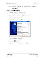
Страница 169: ...w and click the Finish icon See Figure 7 8 Step 0 7 4 VGA Driver Installation To install the VGA driver please do the following Step 1 Access the driver list shown in Figure 7 3 See Section 7 2 Step 2...

Страница 170: ...right 2009 CyberResearch Inc Figure 7 10 VGA Driver Setup Files Extracted Step 6 The Welcome Screen in Figure 7 11 appears Figure 7 11 VGA Driver Welcome Screen Step 7 Click NEXT to continue Step 8 Th...

Страница 171: ...3 643 5000 F 203 643 5001 Branford CT USA www cyberresearch com Figure 7 12 VGA Driver License Agreement Step 9 Read the License Agreement Step 10 Click YES to accept the license agreement and continu...

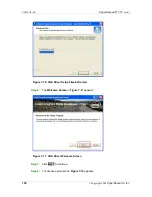
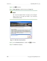
Страница 172: ...e performed as shown in Figure 7 14 NOTE The Found New Hardware Wizard will appear and then disappear during this step Do not adjust any settings in the Found New Hardware Wizard window Figure 7 14 VG...

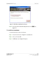
Страница 173: ...VGA Driver Installation Finish Screen Step 16 Select Yes I want to restart the computer now and click FINISH See Figure 7 15 Step 0 7 5 LAN Driver Installation To install the chipset driver please do...

Страница 174: ...earch Inc Figure 7 16 LAN Driver Welcome Screen Step 4 Click NEXT to continue Step 5 The Ready to Install screen in Figure 7 17 appears Figure 7 17 LAN Driver Welcome Screen Step 6 Click NEXT to proce...

Страница 175: ...search com Step 8 The installation progress can be monitored in the progress bar shown in Figure 7 18 Figure 7 18 LAN Driver Installation Step 9 When the driver installation is complete the screen in...

Страница 176: ...abilities to the CZGL AT 16 connect a HD Audio kit or AC 97 audio kit available from CyberResearch Inc Follow the installation applicable to the installed audio kit 7 6 1 AC 97 Driver Installation To...

Страница 177: ...ep 3 Browse to E 4 Audio ALC665 Windows Windows 98Gold 98se Me 2000 XP 2003 32 64 bits A3 84 Figure 7 21 Figure 7 21 AC 97 Audio Driver Options Step 4 Double click the installation file in Figure 7 21...

Страница 178: ...7 The Verification window in Figure 7 23 may appear Figure 7 23 AC 97 Driver Installation Verification Step 8 Click CONTINUE ANYWAY Step 9 When the driver is installed the driver installation finish...

Страница 179: ...And click FINISH to exit the InstallShield Wizard and restart the computer Step 0 7 6 2 HD Audio Driver Installation To install the chipset driver please do the following Step 1 Access the driver list...

Страница 180: ...in Figure 7 26 Step 5 The AC 97 Driver Installation screen in Figure 7 27 appears Figure 7 27 HD Audio Driver Installation Welcome Screen Step 6 Click NEXT to continue Step 7 When the driver is instal...

Страница 181: ...Installation The iSMM Intelligent System Management Module allows hardware functions to be monitored from within the operating system The iSMM can be set to sound an alarm when voltages temperatures o...

Страница 182: ...ents of the directory are displayed Figure 7 30 Figure 7 30 iSMM Installation File Step 6 Double click the iSMM EN V1 11 00 setup file Figure 7 30 Step 7 The iSMM InstallShield Welcome Screen appears...

Страница 183: ...ive P 203 643 5000 F 203 643 5001 Branford CT USA www cyberresearch com Step 9 The License Agreement screen appears Figure 7 32 Figure 7 32 iSMM License Agreement Step 10 Select I accept the terms of...

Страница 184: ...12 The Customer Information screen appears Figure 7 33 Figure 7 33 iSMM Customer Information Step 13 Fill in the User Name and Organization fields which will be automatically filled with the settings...

Страница 185: ...165 25 Business Park Drive P 203 643 5000 F 203 643 5001 Branford CT USA www cyberresearch com Step 15 The Setup Type screen appears Figure 7 34 Figure 7 34 iSMM Setup Type Step 16 Select Complete Fi...

Страница 186: ...h CPU Cards 166 Copyright 2009 CyberResearch Inc Step 18 The Installation Confirmation screen appears Figure 7 35 Figure 7 35 iSMM Installation Confirmation Step 19 Click INSTALL to begin installing t...

Страница 187: ...rd Completed appears when the drivers are finished installing Figure 7 36 Figure 7 36 iSMM InstallShield Wizard Complete Step 21 Click FINISH to exit the installation program Figure 7 36 Step 22 The R...

Страница 188: ...CZGL AT 16 CyberResearch CPU Cards 168 Copyright 2009 CyberResearch Inc Appendix A A BIOS Options...

Страница 189: ...Transfer Auto 101 PIO Mode Auto 101 DMA Mode Auto 102 S M A R T Auto 103 32Bit Data Transfer Enabled 103 Floppy A B 104 Parallel Port Address Disabled 105 Parallel Port Mode Normal 105 Parallel Port...

Страница 190: ...ntroller Enabled 121 Legacy USB Support Enabled 122 USB2 0 Controller Mode HiSpeed 122 IRQ Available 123 DMA Channel Available 124 Reserved Memory Size Disabled 124 Quick Boot Enabled 126 Quiet Boot E...

Страница 191: ...71 25 Business Park Drive P 203 643 5000 F 203 643 5001 Branford CT USA www cyberresearch com Spread Spectrum Mode Enabled 139 Save Changes and Exit 140 Discard Changes and Exit 140 Discard Changes 14...

Страница 192: ...CZGL AT 16 CyberResearch CPU Cards 172 Copyright 2009 CyberResearch Inc Appendix B B Terminology...

Страница 193: ...de volume of the signal A low amplitude signal represents a binary 0 while a high amplitude signal represents a binary 1 BIOS The Basic Input Output System BIOS is firmware that is first run when the...

Страница 194: ...Enhanced Intel SpeedStep Technology EIST allows users to modify the power consumption levels and processor performance through application software The application software changes the bus to core fr...

Страница 195: ...A SATA is a serial communications bus designed for data transfers between storage devices and the computer chipsets The SATA bus has transfer speeds up to 1 5 Gb s and the SATA II bus has data transfe...

Страница 196: ...CZGL AT 16 CyberResearch CPU Cards 176 Copyright 2009 CyberResearch Inc Appendix C C Digital I O Interface...

Страница 197: ...n to the selected address to enable the DIO functions NOTE For further information please refer to the datasheet for the Super I O chipset C 2 DIO Connector Pinouts The following table describes how t...

Страница 198: ...ogram to enable digital I O input functions is listed below MOV AX 6F08H Sets the digital port as input INT 15H Initiates the INT 15H BIOS call C 3 2 Enable the DIO Output Function The BIOS interrupt...

Страница 199: ...CyberResearch CPU Cards CZGL AT 16 CyberResearch Inc 179 25 Business Park Drive P 203 643 5000 F 203 643 5001 Branford CT USA www cyberresearch com Appendix D D Watchdog Timer...

Страница 200: ...INT 15H is used to control the Watchdog Timer INT 15H AH 6FH Sub function AL 2 Sets the Watchdog Timer s period BL Time out value Its unit second is dependent on the item Watchdog Timer unit select in...

Страница 201: ...is necessary to disable the Watchdog Timer otherwise the system resets EXAMPLE PROGRAM INITIAL TIMER PERIOD COUNTER W_LOOP MOV AX 6F02H setting the time out value MOV BL 30 time out value is 48 secon...

Страница 202: ...CZGL AT 16 CyberResearch CPU Cards 182 Copyright 2009 CyberResearch Inc Appendix E E Address Mapping...

Страница 203: ...16 CyberResearch Inc 183 25 Business Park Drive P 203 643 5000 F 203 643 5001 Branford CT USA www cyberresearch com E 1 Direct Memory Access DMA Figure E 1 Direct Memory Access DMA E 2 Input Output IO...

Страница 204: ...CZGL AT 16 CyberResearch CPU Cards 184 Copyright 2009 CyberResearch Inc Figure E 3 Input Output 2 of 2...

Страница 205: ...erResearch CPU Cards CZGL AT 16 CyberResearch Inc 185 25 Business Park Drive P 203 643 5000 F 203 643 5001 Branford CT USA www cyberresearch com E 3 Interrupt Request IRQ Figure E 4 Interrupt Request...

Страница 206: ...CZGL AT 16 CyberResearch CPU Cards 186 Copyright 2009 CyberResearch Inc E 4 Memory Figure E 5 Memory...

Страница 207: ...CyberResearch CPU Cards CZGL AT 16 CyberResearch Inc 187 25 Business Park Drive P 203 643 5000 F 203 643 5001 Branford CT USA www cyberresearch com Index...

Страница 208: ...nector 38 location and pinouts 38 reset CMOS 38 BIOS 91 92 93 98 119 122 127 133 140 C cables ATA flat cable 66 78 dual port USB 84 dual RS 232 cable 79 LPT 81 parallel port 81 SATA drive 82 SATA driv...

Страница 209: ...B cable 84 E electrostatic discharge 27 62 Enhanced Hardware Monitor 21 Ethernet connector external 58 Ethernet controllers 58 external indicators 44 external peripheral interface 86 connection 86 con...

Страница 210: ...nouts 48 L LAN connection 86 LAN connector 58 LCD display 37 backlight inverter connector 37 LPC bus 23 LPC interface 20 LPT cable connection 82 LPT cable 81 LPT connection 81 LVDS display 72 voltage...

Страница 211: ...tion 79 COM 2 location and pinouts 52 connector location and pinouts 52 dual cable 79 RS 232 485 serial port select jumper 71 settings 71 S SATA controller 19 SATA drive 82 cables 82 connection 82 pow...

Страница 212: ...B 2 0 56 USB 1 1 56 USB 2 0 56 121 USB 2 0 port 59 USB cable dual port 84 USB connector internal 56 location and pinouts 56 USB device connection 87 single connector 87 USB port 59 USB2 0 122 V VGA 88...

Страница 213: ...tings and possibly change settings before reinstalling the modules 3 Have a volt meter handy to take measurements of the signals you are trying to measure as well as the signals on the board module or...

Страница 214: ...CZGL AT 16 CyberResearch CPU Cards 194 Copyright 2009 CyberResearch Inc Intentionally Blank...

Страница 215: ...d the sole and exclusive liability of the Seller its successors or assigns in connection with equipment purchased and in lieu of all other warranties expressed implied or statutory including but not l...

Страница 216: ...CZGL AT 16 CyberResearch CPU Cards 196 Copyright 2009 CyberResearch Inc Intentionally Blank...

Страница 217: ......

Страница 218: ...CyberResearch Inc 25 Business Park Drive Branford CT 06405 USA P 203 483 8815 F 203 483 9024 www cyberresearch com...

Отзывы: