Chapter 3
:
Replacing Components and Preventive Maintenance
62
SE500
ULTRA
Hardware Manual
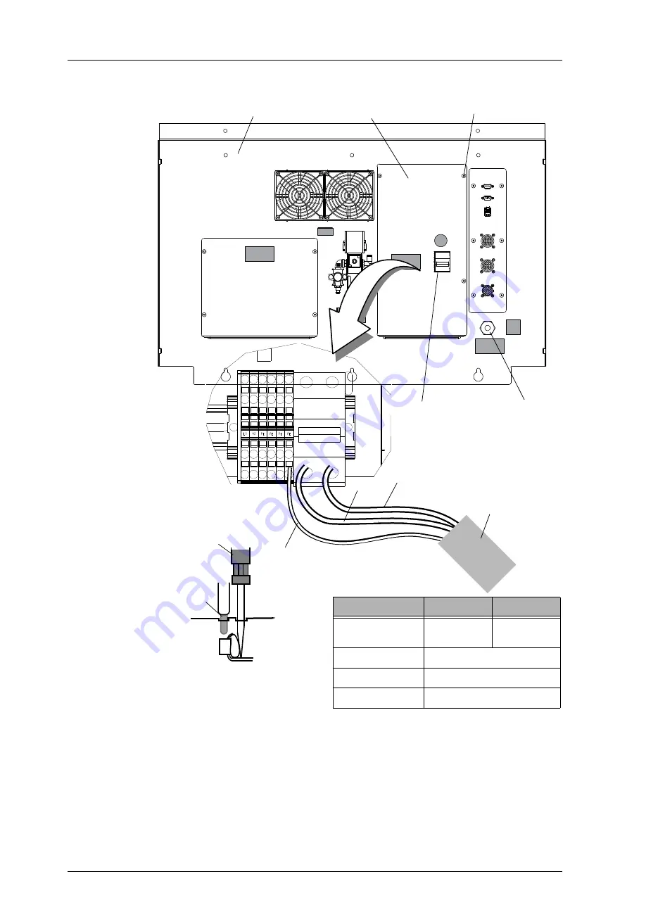
Figure 34.
Replacing the Circuit Breaker
5. Reconnect the wires for outside line and system power.
a.
Insert a screwdriver to release the crimp-style connector.
b.
Insert the stripped portion of the wire into the connector.
c.
Remove the screwdriver to allow the connector to crimp the conductor.
d.
Pull the wire to ensure it is secured.
6. Place the power access cover back onto the panel and secure in place with four screws.
7. Turn the AC main circuit breaker to ON.
PE
PE
PE
N2
L2
PE
N1
L1
N
L
Power access cover
(Loosen) screws (x 4)
Strain relief nut
AC main circuit breaker
(CB1)
Pry open the crimping
connector using a
screwdriver and insert the
conductor.
Stripped wire
Screwdriver
Back Electrical Panel
N
L
GND
Power Cord
(AWG 14–16)
Voltage (VAC)
110 VAC
240 VAC
Power Cord
(AWG)
14
14-16
L Wire
Brown or Black or Red
N Wire
Blue or White
GND Wire
Yellow or Green or Copper
NOTE: The
SE500
ULTRA
does not
comes with the power cord.
Содержание SE500ULTRA
Страница 1: ...SE500ULTRA Hardware Manual ...
Страница 6: ...Contents vi SE500ULTRA Hardware Manual ...
Страница 10: ...x SE500ULTRA Hardware Manual This page is intentionally left blank ...
Страница 28: ...Chapter 1 System Overview 18 SE500ULTRA Hardware Manual Dimensions Figure 8 Front View ...
Страница 30: ...Chapter 1 System Overview 20 SE500ULTRA Hardware Manual ...
Страница 163: ...CyberOptics Corporation 153 AC and DC Distribution Block Diagram AC and DC Distribution Block Diagram ...
Страница 184: ...Chapter 5 System Drawings 174 CyberOptics Corporation ...


