background image

Chapter 4 Operations


29 

RT33020/25/30KE User Manual 


    Fig.4-8 Parallel connection 


4.4.2 Parallel system setting 


Parallel system connection 

For field installation, please connect the cables according to Fig.4-6 and Fig.4-8.   

In order to assure that all units are equally utilized and to comply with relevant wiring rules, 

the following requirements apply: 
1. All units shall be of the same rating and must be connected to the same bypass source. 
2. The bypass and the main input sources must be referenced to the same neutral potential. 
3. Any RCD (Residual Current detecting device), if installed, must be of an appropriate 

setting and located upstream of the common neutral bonding point. Alternatively, the 
device must monitor the protective earth currents of the system. Refer to the High 
Leakage Current Warning in the first part of this manual. 

4. The outputs of all UPS must be connected to a common output bus. 


Parallel system software setting 

To change the parallel system setting, please follow the steps below. 
1. 

With the monitoring software from manufacturer, select the page of “Service Setting” as 
below. 

Содержание RT33020KE

Страница 1: ...User s Manual RT33020 25 30KE Cyber Power Systems Inc www cyberpower com ...

Страница 2: ...Ver 1 0 0 ...

Страница 3: ...iliar with the operation debug and maintenance of the equipment Warning Label The warning label indicates the possibility of human injury or equipment damage and advises the proper step to avoid the danger In this manual there are three types of warning labels as below Labels Description Danger Serious human injury or even death may be caused if this requirement is ignored Warning Human injury or ...

Страница 4: ... 10 minutes for internal discharge Use a multi meter to measure the voltage on terminals and ensure the voltage is lower than 36V before operation Attention The earth leakage current of load will be carried by RCCB or RCD Initial check and inspection should be performed after long time storing of UPS Maintenance Replacement Danger All the equipment maintenance and servicing procedures involving in...

Страница 5: ...for high voltage operation before accepting and using the battery check the appearance the battery If the package is damaged or the battery terminal is dirty corroded or rusted or the shell is broken deformed or has leakage replace it with new product Otherwise battery capacity reduction electric leakage or fire may be caused Before operating the battery remove the finger ring watch necklace brace...

Страница 6: ...omena happen If a battery leaks electrolyte or is otherwise physically damaged it must be replaced stored in a container resistant to sulfuric acid and disposed of in accordance with local regulations If electrolyte comes into contact with the skin the affected area should be washed immediately with water Disposal Warning Dispose of used battery according to the local instructions ...

Страница 7: ...inet Installation 6 2 3 1 Tower Installation 6 2 3 2 Rack Installation 6 2 4 Power Cables 8 2 4 1 Specifications 8 2 4 2 Specifications for Power Cables Terminal 8 2 4 3 External breakers specifications 8 2 4 4 Connecting Power Cables 9 2 5 Control and Communication Cables 9 2 5 1 Dry Contact Interface 10 2 5 2 Communication Interface 13 Chapter 3 LCD Panel 14 3 1 Control and Operation Panel 14 3 ...

Страница 8: ... 5 Maintenance 32 5 1 Precautions 32 5 2 Instruction for Maintaining UPS 32 5 3 Instruction for Maintaining Battery string 32 Chapter 6 Product Specification 34 6 1 Applicable Standards 34 6 2 Environmental Characteristics 34 6 3 Mechanical Characteristic 34 6 4 Electrical Characteristics 35 6 4 1 Electrical Characteristics Input Rectifier 35 6 4 2 Electrical Characteristics Intermediate DC Link 3...

Страница 9: ...lled to provide backup energy once the utility fails The UPS structure is shown in Fig 1 1 Rectifier AC DC Inverter DC AC Charger DC DC Bypass Input Battery Load Static Switch Main Input Fig 1 1 UPS Configuration 1 2 Operation Mode The Tower UPS is an on line double conversion UPS that permits operation in the following modes Normal mode Battery mode Bypass mode Maintenance mode manual bypass ECO ...

Страница 10: ...ch will perform a transfer of the load from the inverter to the bypass source with no interruption in power to the critical AC load Should the inverter be asynchronous with the bypass the static switch will perform a transfer of the load from the inverter to the bypass with power interruption to the load This is to avoid large cross currents due to the paralleling of unsynchronized AC sources This...

Страница 11: ...oads Rectifier AC DC Inverter DC AC Charger DC DC Bypass Input Battery Load Static Switch Main Input Fig 1 6 ECO Mode operation diagram Note There is a short interruption time less than 10ms when transfer from ECO mode to battery mode it must be sure that the interruption has no effect on loads 1 2 6 Auto restart Mode The battery may become exhausted following an extended AC mains failure The inve...

Страница 12: ...Table 1 2 UPS configuration table Components Quantity Remark Dual Input 3 Standard Dry Contact Card 1 Standard Cold start 1 Standard Parallel Card 1 Optional Circuit Breakers 1 Optional Battery 1 Optional 1 4 Appearance and Configuration 1 4 1 Appearance The appearance of the UPS is shown in Fig 1 7 Fig 1 7 UPS Outlook Note Non professionals are forbidden to open the case cover otherwise there may...

Страница 13: ...eration display panel for more details Rear panel As shown in Fig 1 8 the UPS rear panel offers the following components Fig 1 8 UPS rear panel Components Remark RS232 Standard RS485 Standard Connector Standard SNMP Optional Parallel Card Optional USB Optional LBS Optional ...

Страница 14: ... and rear of the UPS are not blocked Allow at least 0 5m of space on each side 3 Condensation to water drops may occur if the UPS is unpacked in a very low temperature environment In this case it is necessary to wait until the UPS is fully dried inside out before proceeding installation and use Otherwise there are hazards of electric shock NOTICE UPS operation in sustained temperature outside the ...

Страница 15: ...lockwise and then insert it 2 3 2 Rack Installation Battery cabinets must be installed firstly because battery cabinets are too heavy And two or more installation personnel are required to install them at the same time Please install them from bottom to top 1 Install the guide rail 2 Put the UPS and battery cabinet on the guide rail fix the units to the service rack shown as Fig 2 3 Fig 2 3 Rack M...

Страница 16: ...he table are based on the 208V system Line to line voltage The size of neutral lines should be 1 5 1 7 times the value listed above when the predominant load is non linear 2 4 2 Specifications for Power Cables Terminal Specifications for power cables connector are listed as Table 2 2 Table 2 2 Requirements for UPS terminal Port Connection Bolt Bolt Aperture Torque Moment Mains input Cables crimped...

Страница 17: ...o the Battery terminal 6 Check to make sure there is no mistake and re install all the protective covers Note mL1 mL2 mL3 standard for Main input phase L1 L2 and L3 bL1 bL2 bL3 standard for Bypass Input phase L1 L2 and L3 Attention The operations described in this section must be performed by authorized electricians or qualified technical personnel If you have any difficulties contact the manufact...

Страница 18: ... Battery trip signal J6 2 BCB_Status Input dry contact function is settable Default BCB Status and BCB Online Alert no battery when BCB Status is invalid J7 1 BCB_Online Input dry contact function is settable Default BCB Status and BCB Online Alert no battery when BCB Status is invalid J7 2 GND_DRY Ground for 24V J8 1 BAT_LOW_ALARM_NC Output dry contact Normally closed function is settable Default...

Страница 19: ...ig 2 6 J2 and J3 for temperature detecting Table 2 5 Description of J2 and J3 Port Name Function J2 1 TEMP_BAT Detection of battery temperature J2 2 TEMP_COM common terminal J3 1 TEMP_ENV Detection of environmental temperature J3 2 TEMP_COM common terminal Note Specified temperature sensor is required for temperature detection R25 5Kohm B25 50 3275 please confirm with the manufacturer or contact t...

Страница 20: ... 24V voltage 20mA drive signal J6 2 BCB_Status BCB contact status connect with the normally open signal of BCB J7 1 BCB_Online BCB on line input normally open BCB is on line when the signal is connecting with J7 2 J7 2 GND_DRY Power ground for 24V Battery Warning Output Dry Contact Interface The default function of J8 is the output dry contact interface which presents the battery warnings of low o...

Страница 21: ...e diagram is shown in Fig 2 10 and description is shown in Table 2 10 Fig 2 10 Integrated warning dry contact interface diagram Table 2 9 General alarm dry contact interface description Port Name Function J9 1 GENERAL_ALARM_NC Integrated warning relay normally closed will be open during warning J9 2 GENERAL_ALARM_NO Integrated warning relay normally open will be closed during warning J9 3 GENERAL_...

Страница 22: ...rs operating status and alarm information As shown in Fig 3 1 The front panel of the UPS can be divided into three parts status indicator LCD display cold start operation key The front panel components of the UPS are described in Table 3 1 Fig 3 1 Front panel of UPS Table 3 1 Description of front panel components Number Name Function LCD Can operate control and query all its parameters running sta...

Страница 23: ...bar Displays the current date and time Log bar Displays alarm messages that appear during the UPS operation Indicator bar Indicates the current running state and power flow of the UPS Buzzer Buzzer control button Touch control Buzzer on Buzzer off 3 3 Main menu The main menu includes Cabinet Data Setting Log Operate and System and it is described in details below 3 3 1 Home Touch Home icon and the...

Страница 24: ... factor Fig 3 5 Data display page main input The main input data page displays voltage frequency current power factor rated input voltage and frequency Fig 3 6 data display page output data The output data page displays the output voltage of each phase the output frequency the output current the output power factor the rated output voltage and the frequency ...

Страница 25: ...page displays key parameters of battery such as battery voltage battery current battery capacity etc 3 3 3 Log Touch the Log icon and the system enters the interface of the Log as it is shown in Fig 3 9 The log is listed in reverse chronological order i e the first on the screen with 1 is the most new which displays the events warnings and faults information and the data and time they occur and di...

Страница 26: ...Incident above disappears 18 Bypass Sequence Error Set Bypass voltage Sequence is reverse 19 Bypass Sequence Error Clear Incident above disappears 20 Bypass Volt Abnormal Set Bypass Voltage Abnormal 21 Bypass Volt Abnormal Clear Incident above disappears 22 Bypass Module Fail Set Bypass Module Fail 23 Bypass Module Fail Clear Incident above disappears 24 Bypass Overload Set Bypass Over load 25 Byp...

Страница 27: ...er 59 On UPS Inhibited Clear Incident above disappears 60 Manual Transfer Byp Set Transfer to bypass manually 61 Manual Transfer Byp Set Cancel to bypass manually 62 Esc Manual Bypass Set Escape transfer to bypass manually command 63 Battery Volt Low Set Battery Voltage Low 64 Battery Volt Low Clear Incident above disappears 65 Battery Reverse Set Battery pole positive and negative are reverse 66 ...

Страница 28: ... Unbalance Clear Incident above disappears 93 DC Bus Over Volt Set DC bus over Voltage 94 DC Bus Over Volt Clear Incident above disappears 95 REC Soft Start Fail Set Rectifier soft start fails 96 REC Soft Start Fail Clear Incident above disappears 97 Relay Connect Fail Set Relay in open circuit 98 Relay Connect Fail Clear Incident above disappears 99 Relay Short Circuit Set Relay shorted 100 Relay...

Страница 29: ...mode for Modbus ASCII and RTU selectable USER Output voltage Adjustment Setting the Output Voltage Bypass Voltage Up Limited Up limited working Voltage for Bypass settable 10 15 20 25 Bypass Voltage Down Limited Down limited working Voltage for Bypass settable 10 15 20 30 40 Bypass Frequency Limited Permitted working Frequency for Bypass Settable 1Hz 3Hz 5Hz BATTERY Battery Number Setting the numb...

Страница 30: ...so on as is shown in the following Fig 3 11 Fig 3 11 System page System page shows UPS rectifier and inverter software version positive and negative bus voltage battery charger voltage UPS fan running time inverter output voltage and inlet outlet temperature 3 3 6 Operate Touch the Operate icon and the system enters the page of the Operate as it is shown in Fig 3 12 Fig 3 12 Operate page The Opera...

Страница 31: ... the battery is no less than 25 Battery Maintenance By touching the icon the system transfers to the Battery mode Thisfunction is used for maintaining the battery which requires the normalityof the bypass and minimum capacity of 25 for the battery Battery Boost By touching the icon the system starts boost charging Battery Float By touching the icon the system starts float charging Stop Test By tou...

Страница 32: ...he system has dual inputs close both of the breakers 3 The LCD in front of the UPS is lit up The system enters the home page as shown in Fig 3 2 4 The LCD home interface shows that the system rectifier is working and the indicator flashes as shown in Fig 4 1 Fig 4 1 Interface of rectifier starting 5 After about 30S the rectifier start is completed the bypass static switch is on and the bypass indi...

Страница 33: ...4 Interface of inverter mode 8 Close the external battery switch the battery indicator flashes and then the UPS charges the battery The UPS works in normal mode As shown in Fig 4 5 Fig 4 5 Interface of normal mode Note When the system starts the stored setting will be loaded Users can browse all incidents during the process of the starting up by checking the menu Log 4 1 2 Start from Battery The s...

Страница 34: ... 4 7 Start from Battery 4 Close the output isolation switch or external output isolation switch to supply the load and the system is working on battery model Note You can use the battery cold start button after the battery is switched on for 1 minute 4 2 Procedure for Switching between Operation Modes 4 2 1 Switching the UPS into Battery Mode from Normal Mode The UPS transfers to Battery model imm...

Страница 35: ... select the icon of Operate and select to turn on the inverter After 60S the system transfers to Normal Mode 4 3 Battery Maintenance If the battery is not discharged for a long time it is necessary to test the condition of the battery Enter the menu Operate as is shown in Fig 4 8 and select the icon Battery maintenance the system transfers into the Battery mode for discharging The system will disc...

Страница 36: ...S2 UPS3 UPS4 Fig 4 6 Parallel diagram The parallel board is located at the back of the UPS cabinet as is shown in Fig 4 7 Fig 4 7 Location of the Parallel board All the parallel cables are designed to be shielded and double insulated and are connected between the UPS to form a loop as shown below in Fig 4 8 ...

Страница 37: ...pass and the main input sources must be referenced to the same neutral potential 3 Any RCD Residual Current detecting device if installed must be of an appropriate setting and located upstream of the common neutral bonding point Alternatively the device must monitor the protective earth currents of the system Refer to the High Leakage Current Warning in the first part of this manual 4 The outputs ...

Страница 38: ...Here the software setting is done Ensure all the output parameters must be set the same Parallel system jumper setting There are different setting of the jumpers on the parallel board and control board for different parallel system Fig 4 10 Connectors on Parallel board PS1409_TF1 Fig 4 11 Connectors on Control board PS1608_CT2 1 Parallel boards settings A For single UPS no need parallel board When...

Страница 39: ... all the connection and settings are finished follow the steps below for the operation of parallel system setup 1 Close the output and input breaker of the first unit Wait for the startup of bypass static switch and rectifier about 90 seconds later the system will transfer to normal mode Check if there is any alarm on LCD and verify the output voltage is correct or not 2 Turn on the second unit as...

Страница 40: ...rs 1 Installation The battery should be placed in dry and cool place with good ventilation Avoid direct sunlight and keep away from heat source When installing ensure the correct connection to the batteries with same specification 2 Temperature The most suitable storage temperature is 20 ºC to 25ºC The battery life will be shortened if the battery is used under high temperature or in deep discharg...

Страница 41: ...s storage transportation use and disposal must comply with the national or local regulations and laws about the disposal of hazardous waste and waste batteries or other standards According to the national laws the waste lead acid battery should be recycled and reused and it is prohibited to dispose of the batteries in other ways except recycling Throwing away the waste lead acid batteries at will ...

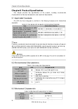
Страница 42: ...40 3 AS 62040 3 VFI SS 111 Note The above mentioned product standards incorporate relevant compliance clauses with generic IEC and EN standards for safety IEC EN AS60950 electromagnetic emission and immunity IEC EN AS61000 series and construction IEC EN AS60146 series and 60950 Warning This product conform the EMC requirements for UPS in Category C3 and it is not suitable for medical equipment 6 2...

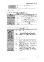
Страница 43: ...meters Battery bus voltage Vdc Rated 240V Quantity of lead acid cells Nominal 40 1 battery 12V 240 1 battery 2V Float charge voltage V cell VRLA 2 25V cell selectable from 2 2V cell 2 35V cell Constant current and constant voltage charge mode Temperature compensation mV cl 3 0 selectable 0 5 0 Ripple voltage 1 Ripple current 5 Equalized charge voltage VRLA 2 4V cell selectable from 2 30V cell 2 45...

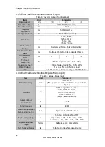
Страница 44: ... 20 80 20 Transient recovery 30ms for step load 20 100 20 Output Voltage THDu 1 from 0 to 100 linear load 6 full non linear load according to IEC EN62040 3 6 4 4 Electrical Characteristics Bypass Mains Input Table 6 8 Bypass Mains Input Item Unit Parameters Rated AC voltage Vac 380 400 415 three phase four wire and sharing neutral with the bypass Overload 125 Long term operation 125 130 for 10min ...

Страница 45: ...5 Efficiency Table 6 9 Efficiency Rated power kVA Unit Parameters Normal mode dual conversion 95 5 ECO mode 98 Battery mode 95 5 6 6 Display and Interface Table 6 10 Display and Interface Display LCD Interface Standard RS232 RS485 Dry Contact Option SNMP Parallel USB ...

Отзывы: