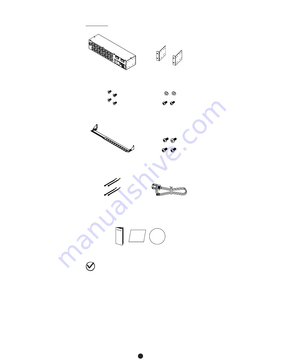
background image

4

Package Contents 

2U Models

PDU

Mounting Brackets x 2 

12 (Flat Head M4 x 8)

Bracket Mounting Screws

6 (M5 x 12) Rack Mounting

Screws/Washers

Cord Retention Tray x 2

12 (M3 x 6) 

Cord Retention Tray

Mounting Screws

            Cable Ties:

Qty: 24 (NEMA outlet PDU)

Qty: 30 (10 IEC outlet PDU)

Qty: 48 (16 IEC outlet PDU)

RJ45/DB9 Serial Port

Connection Cable

Check

Before using, please check to ensure the package contains all the 
items shown above. If there are missing parts, please contact your local 
CyberPower technical support team for assistance.

User's Manual, Registration & Software Download Cards

Users  Manua

l

Registration

Card

PowerPanel

Management Software

Introduction

Содержание PDU31001

Страница 1: ...Power Distribution Unit USER S MANUAL Copyright 2017 Cyber Power Systems Inc All rights reserved ...

Страница 2: ...tallation 15 For 1U Models 15 For 0U Models 15 Power Cord Locking For IEC Type PDU 19 Input Power Cord 19 Output Power Cord 19 Electrical Installation 19 Network Installation 20 Operation 21 Remote Management 21 Local Management 21 LED Indicators 22 Environmental Monitoring optional 22 Device Reset 22 Unattended Automatic Shutdown 22 Firmware Upgrade 23 Troubleshooting 27 Conformance Approvals 27 ...

Страница 3: ... operating the Power Distribution Units PDU Use only the supplied hardware to attach the mounting brackets The PDU must be plugged into a three wire grounded outlet on a circuit that is protected by a fuse or circuit breaker For 15A PDU series please use a 15A circuit protector For 20A PDU series please use a 20A circuit protector For 30A PDU series please use a 30A circuit protector Connection to...

Страница 4: ...Screws 6 M5 x 12 Rack Mounting Screws Washers Cord Retention Tray 6 M3 x 6 Cord Retention Tray Mounting Screws Cable Ties Qty 12 NEMA outlet PDU Qty 27 IEC outlet PDU RJ45 DB9 Serial Port Connection Cable User s Manual Registration Software Download Cards Users Manual Registration Card PowerPanel Management Software ...

Страница 5: ...IEC 320 C19 to NEMA L6 20P PDU81006 PDU81104 PDU71006 PDU41006 PDU41104 PDU31006 PDU31114 Package Contents 0U Models PDU Mounting Brackets with 6 M4x5 Screws 6 M5 x 12 Rack Mounting Screws Washers Cord Retention Tray 6 M3 x 6 Cord Retention Tray Mounting Screws Cable Ties Qty 30 20 outlet PDU Qty 36 24 outlet PDU Qty 63 42 outlet PDU RJ45 DB9 Serial Port Connection Cable User s Manual Registration...

Страница 6: ... 24 NEMA outlet PDU Qty 30 10 IEC outlet PDU Qty 48 16 IEC outlet PDU RJ45 DB9 Serial Port Connection Cable Check Before using please check to ensure the package contains all the items shown above If there are missing parts please contact your local CyberPower technical support team for assistance User s Manual Registration Software Download Cards Users Manual Registration Card PowerPanel Manageme...

Страница 7: ...o F 0o C to 55o C Safety Approvals Certifications UL 60950 1 FCC Class A UL 60950 1 CE FCC Class A All specifications are subject to change without notice A AC Inlet AC Power Cord Used to connect PDU to utility power or UPS B AC Output Receptacles Provides power for connected equipment C Status Indicator Indicates the condition of the PDU eg load or environment status D Multifunction LCD Readout D...

Страница 8: ...tlet is providing power to connected equipment Rear Panel Description A Ground Stud Use to ground the PDU Technical Specifications Model Name PDU81002 PDU71002 PDU41002 PDU31002 PDU81005 PDU71005 PDU41005 PDU31005 PDU81006 PDU71006 PDU41006 PDU31006 Input Nominal Voltage 100 120V 100 240V 200 240V Frequency 50 60Hz Maximum Input Current 16A CE UL Derated Plug Type NEMA L 5 20P Adapter IEC 320 C20 ...

Страница 9: ...r chaining to previous PDU G USB Port Used to upgrade the firmware via a flash drive H AC Output Receptacles Provides power for connected equipment I Serial Port RJ45 modular port Used to connect to a PC and control the PDU locally via SSH Telnet J Daisy Chain Out Port Used for chaining to next PDU K Select Button Used to control the LCD screen and toggle through the available information options ...

Страница 10: ...nal Voltage 100 120V 200 240V Maximum Input Current 16A UL Derated 16A CE 16A UL Derated 16A CE Outlet Type NEMA 5 20R 21 IEC C13 3 IEC C19 18 IEC C13 2 IEC C19 Outlet Number 24 21 3 18 2 Management and Communications Multifunction LCD Readout Voltage Frequency Load Current HW FW Version Network Information Software PowerPanel Business Edition Networking Yes Serial Port RJ45 Sensor Capable Optiona...

Страница 11: ...Indicates the condition of the PDU eg load or environment status D Multifunction LCD Readout Displays various PDU information such as power and load condition E Ethernet Port Used to connect PDU to the network F ENVIROSENSOR Daisy Chain In Port RJ45 modular port Used for ENVIROSENSOR or chaining to previous PDU G USB Port Used to upgrade the firmware via a flash drive H AC Output Receptacles Provi...

Страница 12: ...24 21 3 36 6 Circuit Breaker Yes Management and Communications Multifunction LCD Readout Voltage Frequency Load Current HW FW Version Network Information Software PowerPanel Business Edition Networking Yes Serial Port RJ45 Sensor Capable Optional Physical Dimensions H x W x D 65 5 x 2 2 x 1 9 1665mm x 56mm x 48mm Environmental Humidity 0 to 95 Non condensing Altitude 11480 ft 3500 m Temperature 32...

Страница 13: ...tor switched series only Indicates if the outlet is providing power to connected equipment A Ground Stud Use to ground the PDU Technical Specifications Model Name PDU81003 PDU71003 PDU41003 PDU31003 PDU81007 PDU71007 PDU41007 PDU31007 PDU81008 PDU71008 PDU41008 PDU31008 PDU81009 PDU71009 PDU41009 PDU31009 Input Nominal Voltage 100 120V 200 240V Frequency 50 60Hz Maximum Input Current 24A UL Derate...

Страница 14: ...1 Mounting Bracket Installation Use the provided Mounting Bracket Screws 8 to attach the SHORT Mounting Brackets 2 to the PDU Step 2 PDU Mounting Use the supplied Washers 4 and Screws 4 to secure the PDU to your existing rack system If you plan on attaching the Cord Retention Tray to the PDU you will need to use the LONG Mounting Brackets 2 ...

Страница 15: ...l the screw hole on the Tray and PDU are aligned Attach the Cord Retention Tray to the PDU with the 4 supplied Cord Retention Tray Mounting Screws Tighten the Cord Retention Tray with the screw on it Use the provided Cable Ties to fasten each cord to the Cord Retention Tray Note If the PDUs are intended to install in a high temperature environment please use the Power Cords that could sustain high...

Страница 16: ...he PDU to your existing rack system Step 3 Cord Retention Tray Installation optional Adjust the length of the Cord Retention Tray till the screw hole on the Tray and PDU are aligned Attach the Cord Retention Tray to the PDU with the 8 supplied Cord Retention Tray Mounting Screws Tighten the Cord Retention Tray with the screw on it Installation Guide ...

Страница 17: ...HORT Mounting Brackets 2 to the PDU Step 2 PDU Mounting Use the supplied Washers 2 and Screws 2 to secure the PDU to your existing rack system Vertical Installation For 1U Models Installation Guide For 0U Models Step 1 PDU Mounting Align the Keyhole Mounts to the Keyhole Slots on the rack Insert and slide down to lock firmly into the place ...

Страница 18: ...hat is best for your rack deployment to secure the PDU Use the supplied Washers and Rack Mounting Screws to attach the Mounting Brackets to your existing rack system Align the Keyhole Mounts to the Keyhole Slots on the Mounting Brackets Insert and slide down to lock firmly into the place Method 1 Method 2 ...

Страница 19: ...17 Method 3 Installation Guide ...

Страница 20: ...ntion Tray to the PDU with the supplied Cord Retention Tray Mounting Screws Tighten the Cord Retention Tray with the screw on it Use the provided Cable Ties to fasten each cord to the Cord Retention Tray Note If the PDUs are intended to install in a high temperature environment please use the Power Cords that could sustain high temperature operation Installation Guide ...

Страница 21: ...ent It is extremely important not to exceed the PDUs maximum current load as outlined in the Specifications section In order to determine your total load simply use the LCD display on the front of the PDU to monitor the load being attached The PDU must be plugged into a three wire grounded wall receptacle only The wall receptacle must also be connected to an appropriate branch circuit main with fu...

Страница 22: ... the network connection is ready and power on the PDU 4 The PDU will obtain an IP address from the DHCP server automatically Option 3 Address Resolution Protocol ARP Command 1 Obtain the MAC address from the sticker on the PDU 2 Open a command prompt as an administrator and type the following arp s available IP address MAC address of PDU Example arp s 192 168 20 240 00 0c 15 80 00 01 IP Address MA...

Страница 23: ...Download the CyberPower MIB file and add it to an SNMP supporting management software Default read write community is public private for SNMPv1 SNMPv3 provides a higher security level than SNMPv1 by encrypting the transmitted packet Configure the settings of the SNMPv1 SNMPv3 on Web Interface Local Management LCD Operation The LCD display provides instant information such as voltage current and po...

Страница 24: ...e operating system PowerPanel must be installed on every computer or server for which the shutdown is to take place The software will receive a message from the PDU and will perform the shutdown according to the instructions provided including shut downs at exact times and dates Step 1 PC Configuration 1 Install PowerPanel Business Edition Client on every computer or server that will be part of th...

Страница 25: ...g steps to upgrade the firmware 1 Download the latest firmware from www cyberpower com 2 Extract the file to C 3 Open a command prompt window and navigate to C 4 Login to the PDU with FTP command type C ftp ftp open 192 168 22 126 21 for example 192 168 22 126 is the current IP of the PDU and 21 is the default ftp port for the PDU Connected to 192 168 22 126 220 CyberPower FTP Server Ready User 19...

Страница 26: ... www cyberpower com 2 Open Upgrade and Configuration Utility from Start All Programs CyberPower Upgrade and Configuration Utility 3 Wait for search to finish Shown in Figure 1 Figure 1 4 Check the checkbox to select devices on list of Operation View Shown in Figure 2 Figure 2 5 Make sure Account and Password are valid on selected devices Shown in Figure 3 Figure 3 ...

Страница 27: ...irmware field Shown in Figure 4 Firmware Upgrade Figure 4 8 Same as step 6 assign the data file path in Data field 9 Click OK button to popup a confirm Upgrade Firmware message box 10 Click Yes button starting to upgrade firmware on selected devices Shown in Figure 5 Figure 5 11 The upgrade progress bar will show in Last Action column Shown in Figure 6 Figure 6 ...

Страница 28: ... two files below should be available in order to complete the firmware upgrade process cpsmpdumadata_xxx bin cpsmpdumafw_xxx bin 3 Plug the USB drive into the PDU USB port and press Enter button on the PDU LCD screen to enter Main Menu The USB option will be displayed USB Main USB USB Firmware Firmware Firmware Firmware Upgrade Upgrade Upgrade Upgrade Main Confirm Processing Success Return Yes No ...

Страница 29: ...aler or an experienced radio TV technician for help Notice 1 An unshielded type power cord is required in order to meet FCC emission limits and also to prevent interference to the nearby radio and television reception It is essential that only the supplied power cord by used 2 Use only shielded cables to connect I O devices to this equipment Note THE MANUFACTURER IS NOT RESPONSIBLE FOR ANY RADIO O...

Страница 30: ...terial or workmanship CyberPower will repair or replace it at CyberPower s expense or if CyberPower is unable to or decides not to repair or replace the Product if defective within a reasonable time CyberPower will refund to you the full purchase price you paid for the Product purchase receipt showing price paid is required Who Pays for Shipping We pay when we send items to you you pay when you se...

Страница 31: ...et Control 2 Outlet Configuration Network Setting Physical MAC Address 00 0C 15 40 08 A9 1 System IP 192 168 24 20 2 Subnet Mask 255 255 255 0 3 Default Gateway 192 168 24 254 4 DHCP Enabled 5 Http Port 80 6 Http Access Enabled System Configuration 1 Date mm dd yyyy 11 11 2011 2 Time hh mm ss 17 17 25 3 Name PDU20SW8FNET 4 Contact Administrator 5 Location Server Room Account Setting 1 Administrato...

Страница 32: ...y Step 3 Choose an installation directory Select Next Shown in Figure 2 Figure 2 Step 4 Select Install to comfirm the settings and install Shown in Figure 3 Figure 3 Step 5 Select Finish to finalize the installation Shown in Figure 4 Figure 4 ...

Страница 33: ...teway address This allows the device s to function properly on the network and interface with CyberPower Management Console Step 1 Select the appropriate PDU device from the Equipment List Shown in Figure 6 Figure 6 Equipment List Figure 5 Power Device Network Utility Note If the PDU does not appear on the list click the Refresh button to rescan the network If it still does not appear ensure that ...

Страница 34: ...vice at the Authentication menu Shown in Figure 9 Note The default username is cyber and the default password is cyber Advanced Settings Timeout Settings The Timeout Setting Shown in Figure 10 Edit Timeout Settings is used to specify the wait time when scanning for network PDU devices When there are many devices on the local network it may take extended periods of time to locate all the devices Th...

Страница 35: ...Cyber Power Systems Inc www cyberpower com K01 0000545 01 ...

Отзывы: