background image

15 


life.


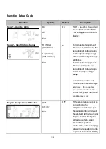
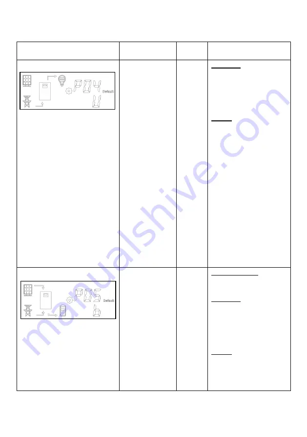
Page 4 - Output Source Priority 


U (Utility) 

P (PV) 

ESC 

U(Utility) 


Utility first 

Utility as first priority supplies 

power to loads. 

When utility is not available, 

solar and battery will supply 

power to loads. 

PV first 

Solar as first priority supplies 

power to loads.   

When solar energy is not 

sufficient, battery will work 

together to supply power to 

the loads. 

When one of the following 

conditions occur, utility will 

supply power: 

1. 

Solar energy does not 

exist. 

2. 

Low battery warning or 

battery voltage reaches 

pre-set transfer value in 

Page 6 (P06). 


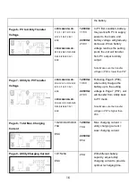
Page 5 - Charging Source Priority 


B (Both) 

U (Utility) 

P (PV) 

ESC 

B (Both) 


Both Utility & PV 

Solar and utility charge the 

battery together. 

Utility first 

Utility as first priority charges 

the battery.   

When utility power is not 

available, solar will charge 

the battery. 

PV first 

Solar power as first priority 

charges the battery.   

When solar power is not 

available, utility will charge 

Содержание CPD1200EO12LCD

Страница 1: ...Hybrid Inverter CPD1200EO12LCD CPD2200EO24LCD User s Manual ...

Страница 2: ...2 ...

Страница 3: ...k 5 2 3 Power Requirements of Your Equipment 7 2 4 Hardware Installation Guide 7 3 DEFINITIONS FOR ILLUMINATED LCD INDICATORS 10 4 OPERATION CONFIGURATION 13 Power On Off 13 Function Setup 13 Audible Alarm 13 Function Setup Guide 14 5 TROUBLESHOOTING 19 6 TECHNICAL SPECIFICATIONS 21 APPENDIX PV MODULE SELECTION 22 ...

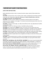
Страница 4: ...vent accumulation and concentration of hydrogen gas at the top of the compartment CAUTION A battery can present a risk of electrical shock and high short circuit current When working on batteries remove watches rings or other metal objects Use tools with insulated handles CAUTION Hazardous live parts inside can be energized by the battery even when the AC input power is disconnected CAUTION To avo...

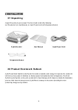
Страница 5: ...onverts renewable solar energy from panels into usable AC and store excess power in batteries as backup power during blackout and emergencies The Solar Hybrid Inverter System comes with a small and compact design which helps to simplify the installation process With Green thinking in mind CyberPower is always in the lead in providing the most pioneering energy saving solution Hybrid Inverter Input...

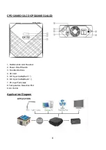
Страница 6: ...PD2200EO24LCD 1 Multifunction LCD Readout 2 Power On off Switch 3 Function Buttons 4 AC Inlet 5 DC Input Cable Red 6 DC Input Cable Black 7 PV Input Terminals 8 Temperature Detection Port 9 AC Outlet Application Diagram ...

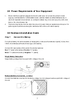
Страница 7: ...e keep the load below 80 of the unit s rated capacity 2 4 Hardware Installation Guide Step 1 Connect the Battery For optimal battery life and reasonable recharging time make sure the batteries capacity no less than 100Ah Use batteries with same brand type and capacity Connect DC input cables of this product to external batteries Red cable to the battery s Positive polarity Black cable to the batte...

Страница 8: ...r close to batteries so that the unit can detect the ambient temperature and control the utility charger with compensation Step 3 Connect the Solar Panel CAUTION In order to switch off the power from PV for the need of maintenance and service please install a circuit breaker between the product and PV module CAUTION To reduce risk of injury use appropriate cables for PV connection The wiring can o...

Страница 9: ...o ensure that the battery s maximum charge capacity is achieved To recharge the battery and maintain optimal battery charge simply leave the unit plugged into a wall outlet at all times The battery can be charged whether the unit is turned on or off DO NOT connect Neutral of the Power Distribution Box to a the OUTPUT Neutral of this product or b the INPUT Neutral of connected equipment Otherwise r...

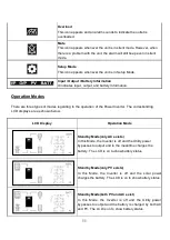
Страница 10: ...l Mode Power On The Power Inverter is turned on Standby Mode Power Off The Power Inverter is off while the LCD display remains on Utility Power Utility power source supplies AC power Solar Power Solar power source supplies to load or battery Load Capacity The approximate load capacity of the unit s outlet in 25 increments Battery Capacity The approximate battery capacity and charging status in 25 ...

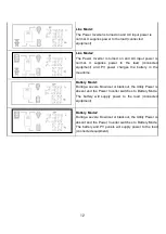
Страница 11: ... regarding to the operation of the Power Inverter The corresbonding LCD displays are as shown below LCD Display Operation Mode Standby Mode only AC exists In this Mode the Inverter is off and the Utility power bypasses to output and in the meantime charges the battery The LCD is on to show battery status Standby Mode only PV exists In this Mode the Inverter is off and the solar power charges the b...

Страница 12: ...ent and PV power charges the battery in the meantime Battery Mode1 During a severe brownout or blackout the Utility Power is absent and the Power Inverter switches to Battery Mode The battery will supply power to the load connected equipment Battery Mode2 During a severe brownout or blackout the Utility Power is absent and the Power Inverter switches to Battery Mode The battery and PV panels will ...

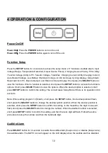
Страница 13: ...options Short press SELECT button to view the options When the desired option is selected short press SETUP button to confirm the setting The unit will leave Setup Mode if there is no operation in 60 seconds Note When setting program 14 kwh short press the SETUP button the decimal point will flash short press the SELECT button to change the decimal point s position When the desired position is sel...

Страница 14: ...w For connected equipment that are sensitive to the fluctuation of voltage range narrow the input voltage range Note The transfer time will increase while the input voltage gets lower If the connected equipment is sensitive to the transfer time power interruption condition may occur Page 3 Temperature Detection OFF 40 50 ESC OFF If the temperature sensor is connected to the temperature detection p...

Страница 15: ...ds When one of the following conditions occur utility will supply power 1 Solar energy does not exist 2 Low battery warning or battery voltage reaches pre set transfer value in Page 6 P06 Page 5 Charging Source Priority B Both U Utility P PV ESC B Both Both Utility PV Solar and utility charge the battery together Utility first Utility as first priority charges the battery When utility power is not...

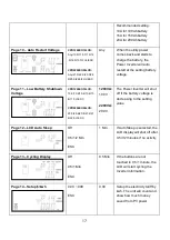
Страница 16: ...Page 7 Utility to PV Transfer Voltage CPD1200EO12LCD FUL 12 0 12 3 12 5 12 8 13 0 13 3 13 5V ESC CPD2200EO24LCD FUL 24 0 24 5 25 0 25 5 26 0 26 5 27 0V ESC 1200VA 13 5V 2200VA 27 0V Following Page 6 P06 when utility charges the battery up to the setting voltage in Page 7 P07 unit will transfer from Utility back to PV mode Note Make sure the transfer voltage in P07 is higher than P06 Page 8 Total M...

Страница 17: ... 0 10 2 10 4 10 6 10 8 11 0V ESC CPD2200EO24LCD 20 0 20 4 20 8 21 2 21 6 22 0V ESC 1200VA 10 0V 2200VA 20 0V The Power Inverter will shut off if the battery voltage is decreasing to the setting value Page 12 LCD Auto Sleep Off 0 5 1 2 Min ESC 1 Min If Auto Sleep is selected the LCD display will shut off after 0 5 1 2 minutes if no activity Page 13 Cycling Display Off 0 5 1 Min ESC 0 5 Min If the b...

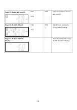
Страница 18: ...V ESC YES ESC User can reset the value of kwh from PV Page 16 Back to Default ESC Yes ESC Select Yes to restore the factory default settings Page 17 Return to Status Display Press the Setup button to go back to the status display ...

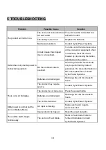
Страница 19: ...rvicing of the DC fuse should only be performed by trained personnel For more information on DC fuse replacement contact CyberPower Systems Batteries are discharged Recharge the unit for at least 8 hours The product may require service Contact CyberPower Systems There is no LCD display The product is not turned on Press the power button Batteries are discharged Recharge the unit for at least 8 hou...

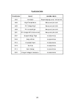
Страница 20: ...cond A88 PV Voltage High Beep every second A89 PV Current High Beep every second A91 PV Charger NTC Disconnect Beep every second E07 Output Voltage High Constant tone E09 Output Short Constant tone E14 Overload Fault Constant tone E18 Fan Fail Constant tone E13 Over Charge Constant tone E25 Output Voltage Unbalance Constant tone ...

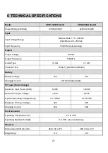
Страница 21: ...UN Transfer Time 8ms Typical Narrow Mode Battery Battery Voltage 12V 24V Charging Current 10 15 20A Adjustable PV Input Solar Charger Maximum Input Power Watt 600W 1200W Nominal PV Input Voltage 12Vdc 24Vdc Optimal Operating Voltage Range 15 18VDC 30 36VDC Maximum PV Input Voltage 40V 55V Charging Current 50A 50A Environmental Operating Temperature C 0 C to 40 C Operating Relative Humidity 0 to 90...

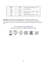
Страница 22: ...rements a Total Voc Product s max PV input voltage b Vmp falls within Product s optimal operating voltage range If one PV module cannot meet this requirement connect multiple PV modules in series to increase the total voltage Example for CPD1200EO12LCD After considering Voc of PV module not exceeds 40VDC and Max Vmp within 15 18VDC we can choose PV module with below specification Pmax 85W Max PV m...

Страница 23: ...A CAUTION Ensure that Open Circuit Voltage Voc of PV modules not exceeds 40V for CPD1200EO12LCD and 55V for CPD2200EO24LCD or else the product may be damaged If PV voltage or current is out of normal range the unit will stop solar charging and send a warning code For more information visit www cyberpower com All rights reserved Reproduction without permission is prohibited ...

Страница 24: ...24 ...

Страница 25: ......

Отзывы: