CVI ViAC-RTK, Инструкция по установке и эксплуатации
CVI ViAC-RTK - современное и эффективное устройство для навигации. Установочное и операционное руководство доступно для загрузки совершенно бесплатно на manualshive.com. Этот автономный РТК приемник гарантирует высокую точность и надежность в работе.
Поделиться
Скачать


Отзывы:
Нет отзывов
Похожие инструкции для ViAC-RTK

SIP-T4X
Бренд: Yealink Страницы: 4

SIP-T4X
Бренд: Yealink Страницы: 148

SIP-T32G
Бренд: Yealink Страницы: 2

SIP-T54S
Бренд: Yealink Страницы: 131

SIP-T48S
Бренд: Yealink Страницы: 159

T48G
Бренд: Yealink Страницы: 9

SIP-T23P
Бренд: Yealink Страницы: 3

UNIVERGE SV8100 DT7 SERIES
Бренд: NEC Страницы: 16

A510H
Бренд: Gigaset Страницы: 48

IP 500
Бренд: Perfectone Страницы: 37

9112i
Бренд: Vertical Страницы: 146

5560
Бренд: Mitel Страницы: 42
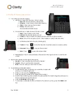
VVX 450
Бренд: Clarity Страницы: 3

ErisTerminal SIP Deskset VSP715A
Бренд: VTech Страницы: 4

MDU 110
Бренд: Häfele Страницы: 64

SIP-T46U
Бренд: Yealink Страницы: 14

KX-NT553
Бренд: Panasonic Страницы: 8

OpenScape Desk Phone IP 35G
Бренд: Unify Страницы: 2


