I.L. 29C171
Page 4
Effective 3/98
d.
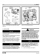
Push circuit breaker handle towards the ON position
and hold while sliding UVR plug-in module into slots
in trip unit (Figure 2-4) until retaining clip snaps into
trip unit. For terminal block assemblies, slide termi-
nal block into mounting slot on side of base as plug-
in module is being positioned.
For a UVR having rear or opposite-side exiting pig-
tail leads, thread leads through in side of base
before attempting to insert the mounting bracket.
Pigtail leads exiting in this manner should be eased
through trough as mounting bracket is inserted into
trip unit retaining slots. Use center trough also for
leads exiting the side of the circuit breaker.
LEADS SHOULD BE FORMED AND ROUTED TO
CLEAR ALL MOVING PARTS WHEN ACCESSORY IS
PROPERLY INSTALLED. PIGTAIL WIRES COULD
BE DAMAGED IF IN CONTACT WITH MOVING
PARTS.
2-9.
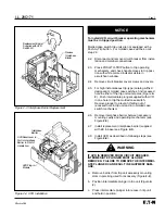
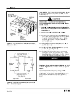
Route wiring to meet installation requirements
(Figure 2-5). If required, complete routing of leads
of opposite side through rear wiring trough.
FAILURE TO KEEP FINGERS AWAY FROM MOVING
PARTS CAN CAUSE PERSONAL INJURY. WHEN
CHECKING ACCESSORY, DO NOT PUT FINGERS
NEAR MOVING PARTS INSIDE CIRCUIT BREAKER
CASE. SPRINGS CAUSE INTERNAL PARTS TO
MOVE QUICKLY AND WITH FORCE.
2-10. Perform mechanical check of UVR after installa-
tion:
a.
WIth the circuit breaker still electrically isolated,
reset the circuit breaker.
b.
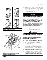
Mechanical check. Using a small flat-blade screw-
driver, (Figure 2-6), push in and hold solenoid
plunger. Switch circuit breaker to ON. Release
solenoid plunger and check that circuit breaker trips.
c.
Reset circuit breaker handle and check that handle
arm moves reset lever to reset the solenoid plunger.
d.
If mechanical check does not trip circuit breaker,
see if UVR and intermediate plunger are correctly
installed. If UVR and intermediate plunger are cor-
NOTICE
Figure 2-5 Accessory WIring Options
Figure 2-6 Screwdriver Depressing Undervoltage
Release Mechanism Solenoid Plunger
Rear Exiting Leads
(Preferred)
Terminal Block
Side Exiting Leads
Opposite-Side
Exiting Leads
Solenoid
Plunger
Flatblade
Screwdriver
!
WARNING
Содержание E2 L
Страница 7: ...I L 29C171 Page 7 Effective 3 98...

