Make sure that the trip unit is suitable for the intended
installation by comparing nameplate data with any exist-
ing equipment and system requirements. Inspect the trip
unit for completeness, and check for damage before
installing it in the circuit breaker frame.
Remove and SAVE the Jumper plug assembly (a 12
position housing) from the trip unit (see Figure 3-2).
Remove the wire-retaining bracket from the right pole of
the trip unit.
Trip unit center retaining screw is captive in the trip
unit conductor; the remaining retaining screws (2
for a 3-pole trip unit) are supplied with the frame.
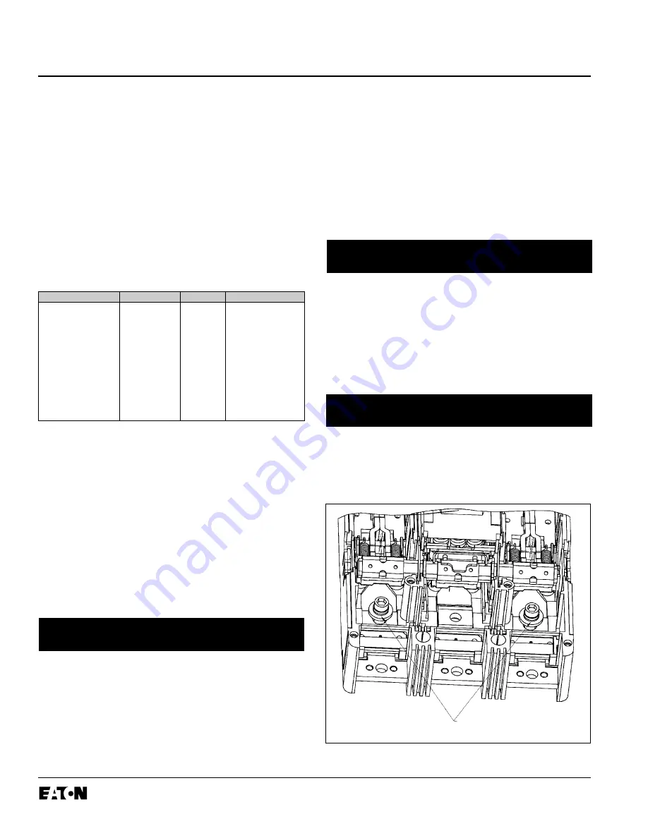
Remove circuit breaker pan-head cover screws, and
covers. Remove trip unit outer pole screws and red
plastic washers from the frame. Discard red plastic
washers (Figure 3-1).
The two trip unit outer pole retaining screws may be
placed in the trip unit conductor holes at this time. If
preferred, a 5/16 inch hexagonal-head wrench may
be used to position the screws when the trip unit is
in the base.
The Digitrip OPTIM 550 Trip Unit is completely self con-
tained and when the circuit breaker is closed, requires
no external power to operate its protection systems. It
operates from current signal levels and control power
derived through current sensors integrally mounted in
the trip unit.
Digitrip OPTIM 550 Trip Units are suitable for 50/60 Hz
AC applications only. For DC applications, a thermal-
magnetic trip unit should be used.
The Digitrip OPTIM 550 Trip Unit for the L-Frame is
available in 3 different types and four different maximum
ampere ratings (Table 1.1).
➀
Ground Fault Alarm trip units do NOT provide ground fault protection.
2.0 UL LISTED DEVICES
The Digitrip OPTIM 550 Trip Unit is listed in accordance
with Underwriters Laboratories, Inc. Standard UL489,
under file E7819 and satisfies the applicable require-
ments of the International Electrotechnical Commission
(IEC) recommendations for molded case circuit break-
ers.
3.0 INSTALLATION
The installation procedure consists of inspecting and
installing the trip unit and rating plug. To install the trip
unit, perform the following steps.
If required, internal accessory installation should be
done before the circuit breaker is mounted and con-
nected. Refer to the individual accessory instruction
leaflets.
I.L. 29C508B
Page 2
Effective 9/00
Table 1.1 Digitrip OPTIM 550 Trip Unit Types
NOTICE
NOTICE
Catalog Number
Max Amps
Version
Description
LEP3125T52
125A
LSI
Non-ground Fault
LEP3125T56
125A LSIG
Ground
Fault
LEP3125T57
➀
125A
LSIA
Ground Fault Alarm
LEP3250T52
250A
LSI Non-ground
Fault
LEP3250T56
250A
LSIG
Ground Fault
LEP3250T57
➀
250A
LSIA
Ground Fault Alarm
LEP3400T52
400A
LSI
Non-ground Fault
LEP3400T56
400A
LSIG
Ground Fault
LEP3400T57
➀
400A
LSIA
Ground Fault Alarm
LEP3600T52
600A
LSI
Non-ground Fault
LEP3600T56
600A
LSIG
Ground Fault
LEP3600T57
➀
600A
LSIA
Ground Fault Alarm
Figure 3-1 Preliminary Preparation
NOTICE
Remove and Dispose
of Red Spacers
Содержание Digitrip OPTIM 550
Страница 10: ...I L 29C508B Page 10 Effective 9 00...
Страница 11: ...I L 29C508B Page 11 Effective 9 00...


