background image

1.2 | GENERAL RULES AND PRECAUTIONS

MAINTENANCE INFORMATION IS FOR USE 

BY TRAINED PERSONNEL ONLY.

NEVER REACH BETWEEN SCISSORS 

LINKS OR PROP UP PLATFORM UNLESS 

MAINTENANCE PINS ARE IN PLACE.

SECTION 1 | SAFETY

FAILURE TO FOLLOW THIS WARNING WILL CAUSE 

DEATH OR PERSONAL INJURY.

“DANGER” indicates an imminently hazardous situation, 
which, if not avoided, will result in death or serious 
injury.

FAILURE TO FOLLOW THIS WARNING MAY CAUSE 

DEATH OR PERSONAL INJURY.

“WARNING” indicates a potentially hazardous situation, 
which, if not avoided, could result in death or serious 
injury

FAILURE TO FOLLOW THIS WARNING MAY CAUSE 

INJURY OR DAMAGE TO EQUIPMENT.

“CAUTION” indicates a potentially hazardous situation 
which, if not avoided, could result in minor or 
moderate injury or damage to equipment

CAUTION

DANGER

WARNING

An operator of any type of work platform is subject to certain hazards that cannot be protected by mechanical 
means. It is therefore essential that operators be competent, careful, physically and mentally fit and thoroughly 
trained in safe operation of this machine.

Although Custom Equipment, LLC conforms to specified EN: 280, it is the responsibility of the owner to instruct 
operators with the safety requirements made not only by Custom Equipment, LLC, but by the various safety boards 
in your area, as well as additional requirements set forth by EN: 280. If you come across a situation that you think 
might be unsafe, stop the platform and request further information from qualified sources before proceeding.

1.1 | SAFETY SYMBOLS

MAINTENANCE & TROUBLESHOOTING
HB-P4.5/HB-P5.0

SUPO-648

REV G

6

SECTION 1 | SAFETY

1.3 | STABILITY TESTING

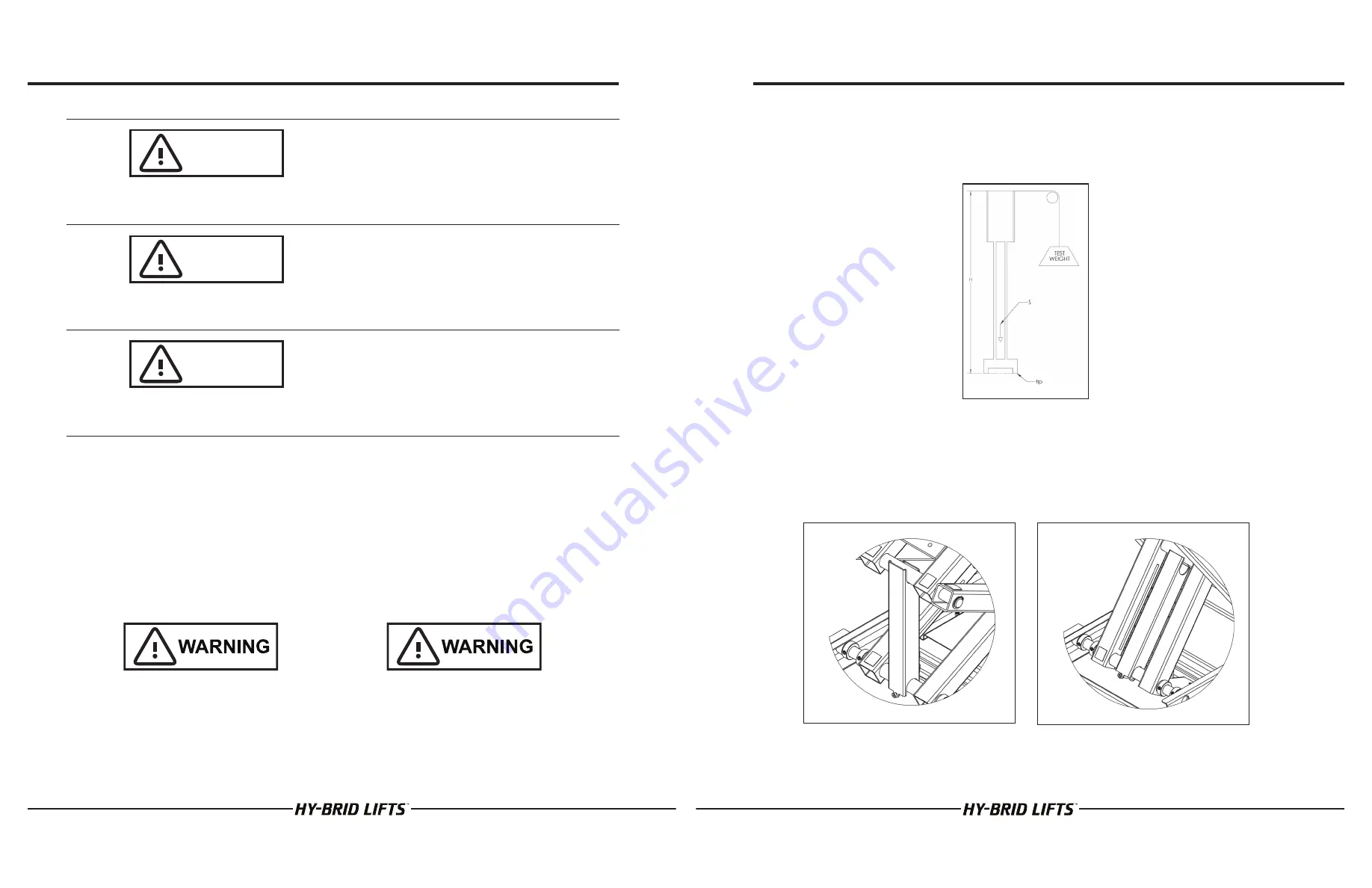
The HB-P4.5 and HB-P5.0 have been stability tested to standards EN280 or AS 14180.  The most adverse stability test 
is the stationary, lateral slope configuration for both units.  The overturning moment created by the test loads and 
forces is equivalent to a test on an unloaded machine on a level surface, as shown in the figure below.  For the HB-
P4.5 and the HB-P5.0, the test weight/pull force is 22.8 kg / 50 lb.

1.4 | SAFETY GUIDELINES

Maintenance Lock

The maintenance lock must be placed into position whenever the machine is being serviced in the raised or partially 
raised position.  Serious injury and/or death could result if maintenance lock is not used properly.

FIGURE 1: Equivalent Stability Test

FIGURE 2: Maintenance PIN Lock Use

FIGURE 3: Maintenance PIN Lock Storage

MAINTENANCE & TROUBLESHOOTING
HB-P4.5/HB-P5.0

SUPO-648

REV G

7

Содержание HY-BRID LIFTS I HB-P4.5

Страница 1: ...MAINTENANCE TROUBLESHOOTING MANUAL PUSH AROUND AERIAL WORK PLATFORM SUPO 648 REV G HB P4 5 HB P5 0 SERIES I BY CUSTOM EQUIPMENT LLC ...

Страница 2: ...safety manual is considered a part of the work platform and contains instructions and operating procedures essential to properly and safely operate the Custom Equipment Hy Brid Lift Users must read and understand all information in the Safety and Operations Manual before operation THE OPERATION AND SAFETY MANUAL MUST BE READ AND UNDERSTOOD PRIOR TO OPERATING THE MACHINE The user operator should no...

Страница 3: ...HEMATIC 18 4 2 ELECTRICAL SCHEMATIC 20 SECTION 5 WIRING DIAGRAMS 22 5 1 WIRING DIAGRAM 22 5 2 UPPER CONTROL WIRING DIAGRAM 24 SECTION 6 TROUBLESHOOTING FLOWCHARTS 26 6 1 TROUBLESHOOTING FLOWCHART POWER 26 6 2 TROUBLESHOOTING FLOWCHART ELEVATING 28 6 3 TROUBLESHOOTING FLOWCHART LOWERING 30 SECTION 7 PARTS DIAGRAMS 32 7 1 SAFETY AND CONTROL DECALS 32 7 2 MAIN POWER SAFETY CIRCUIT 33 7 3 ELEVATE LOWE...

Страница 4: ... the responsibility of the owner to instruct operators with the safety requirements made not only by Custom Equipment LLC but by the various safety boards in your area as well as additional requirements set forth by EN 280 If you come across a situation that you think might be unsafe stop the platform and request further information from qualified sources before proceeding 1 1 SAFETY SYMBOLS MAINTE...

Страница 5: ...gs and cautions on machine and in manual Keep oil grease water etc wiped from standing surfaces and handholds Before making any adjustments lubricating or performing any other maintenance shut off all power controls Battery should always be disconnected during replacement of electrical components Keep all support equipment and attachments stowed in their proper place Use only approved nonflammable ...

Страница 6: ...nless water level is below the plates Slide cabinet open to access battery Remove battery caps and check fluid level Fill each cell if needed to split ring with distilled water Reinstall caps Wash all dirt debris acid etc off battery whenever corrosion is detected Use a solution of 5ml baking soda per 0 95 liters of warm water Coat terminals with a commercially available coating Close cabinet and l...

Страница 7: ...al use no components should require adjustment Contact the manufacturer if adjustments are required 2 6 EXAMINATION REPAIR REPLACEMENT OF LIMITED LIFE COMPONENTS With proper use regular battery charging and regular inspection there are no limited life components that require routine replacement 2 7 SAFETY DEVICES AND SYSTEMS REQUIRING CHECKS Check safety functions as part of daily inspection Check...

Страница 8: ...rty machine cannot be properly inspected Y Yes Acceptable N No Unacceptable R Repaired Description Y N R VISUAL INSPECTIONS Check that there are no damaged dented or bent structural members ڧ ڧ ڧ There are no loose or missing parts ڧ ڧ ڧ Check that warning and instructional labels are legible and secure Ensure that load capacity is clearly marked ڧ ڧ ڧ Check the platform rails and safety gate for ...

Страница 9: ...TED SERVICED AND ADJUSTED TO MANUFACTURER S REQUIREMENTS BY A QUALIFIED MECHANIC PRIOR TO EACH SALE LEASE OR RENTAL AND EVERY 3 MONTHS OR 150 HOURS WHICHEVER COMES FIRST MODEL SERIAL NUMBER Check each item listed below Use proper operating service and maintenance manual for specific information and settings If an item is found to be unacceptable make the necessary repairs and check the repaired box...

Страница 10: ...ICAL REFERENCES 4 1 HYDRAULIC SCHEMATIC Part No HS HB P4 5 5 0 MAINTENANCE TROUBLESHOOTING HB P4 5 HB P5 0 SUPO 648 REV G 18 SECTION 4 TECHNICAL REFERENCES MAINTENANCE TROUBLESHOOTING HB P4 5 HB P5 0 SUPO 648 REV G 19 ...

Страница 11: ... 72 5 1 6 SECTION 4 TECHNICAL REFERENCES MAINTENANCE TROUBLESHOOTING HB P4 5 HB P5 0 SUPO 648 REV G 20 0 0 2 3803 62 12 62 12 23 5 7 83 9 9 62 12 23 5 7 2 1 9 9 12 5 9 6 5 37 21 7 1 7 5 6 6 5 9 63 2 211 7 216 72 7 0 5 21 027 21 50 237 6 XVWRP TXLSPHQW QF 5LFKILHOG 3KRQH 7 3 57 12 6 75 6 0 7 3 6 1 7 7 7 37 21 17 1 86 21 25 7 385326 25 7 6 2 1 SECTION 4 TECHNICAL REFERENCES MAINTENANCE TROUBLESHOOTI...

Страница 12: ...BLESHOOTING HB P4 5 HB P5 0 SUPO 648 REV G 22 833 5 21752 12 1 50 8 5 29 5 2 0 7 6 7 237 21 6 1 21 7 6 25 1 5 1 XVWRP TXLSPHQW QF 5LFKILHOG 3KRQH 7 5 1 5 0 3 6 2 127 6 5 1 1 7 7 7 37 21 17 1 86 21 25 7 385326 25 7 6 2 1 63 0 7 6FKHPDWLF 5 1 5 9 6 5 37 21 2 1 7 5 9 0RYH HDFRQ LUH WR 2SS 6LGH RI LVF 6Z 2 6 7 2 7 3352 SECTION 5 WIRING DIAGRAMS MAINTENANCE TROUBLESHOOTING HB P4 5 HB P5 0 SUPO 648 REV ...

Страница 13: ... 17 1 35235 7 5 72 86720 48 30 17 1 6 2 1 1 MAINTENANCE TROUBLESHOOTING HB P4 5 HB P5 0 SUPO 648 REV G 24 SECTION 5 WIRING DIAGRAMS 12 5 12 1 0 7 6 7 77 77 3803 62 83 2 6 25 1 5 1 XVWRP TXLSPHQW QF 5LFKILHOG 3KRQH 7 3 835 7 6 2 127 6 5 1 3 7 7 21 7 7 7 37 21 17 1 86 21 25 7 385326 25 7 6 2 1 63 0 7 LULQJ LDJUDP 5 1 5 9 6 5 37 21 2 1 7 5 9 77 0 7 5 5 1 6 2 6 7 2 7 3352 MAINTENANCE TROUBLESHOOTING H...

Страница 14: ...RTS 6 1 TROUBLESHOOTING FLOWCHART POWER Troubleshooting Step 1 Main Power MAINTENANCE TROUBLESHOOTING HB P4 5 HB P5 0 SUPO 648 REV G 26 SECTION 6 TROUBLE SHOOTING FLOWCHARTS MAINTENANCE TROUBLESHOOTING HB P4 5 HB P5 0 SUPO 648 REV G 27 ...

Страница 15: ...S 6 2 TROUBLESHOOTING FLOWCHART ELEVATING Troubleshooting Step 2A Elevating MAINTENANCE TROUBLESHOOTING HB P4 5 HB P5 0 SUPO 648 REV G 28 SECTION 6 TROUBLE SHOOTING FLOWCHARTS MAINTENANCE TROUBLESHOOTING HB P4 5 HB P5 0 SUPO 648 REV G 29 ...

Страница 16: ...TS 6 3 TROUBLESHOOTING FLOWCHART LOWERING Troubleshooting Step 2B Lowering MAINTENANCE TROUBLESHOOTING HB P4 5 HB P5 0 SUPO 648 REV G 30 SECTION 6 TROUBLE SHOOTING FLOWCHARTS MAINTENANCE TROUBLESHOOTING HB P4 5 HB P5 0 SUPO 648 REV G 31 ...

Страница 17: ...BSITE DE679 DECAL HYDR FLUID DE706 DECAL UPR DE718 DECAL CE MARK DE723 DECAL WHEEL LOAD HB P4 5 DE727 DECAL KEEP DE728 DECAL CLEAR DE729 DECAL WHEEL LOAD HB P5 0 DE730 DECAL OL ALARM DE731 DECAL QR CODES DE739 DECAL LWR DE740 DECAL LWR PWR DE742 DECAL CAPACITY 550 1P I WO SO MAINTENANCE TROUBLESHOOTING HB P4 5 HB P5 0 SUPO 648 REV G 32 7 2 MAIN POWER SAFETY CIRCUIT SECTION 7 PARTS DIAGRAMS Item Pa...

Страница 18: ...Lever 10 HARD 650 7 16 Shaft Collar 11 HYDR 044 FL3 Hirschmann Connector with Diode 12 144 21 012 51 K Hydraulic Cylinder 13 HARD 644 06 Emergency Down Cable 13 HARD 644 07 Emergency Down Cable Handle only 14 HYDR 674 Start Solenoid 12 V 15 HYDR 665 Up Valve 15 HYDR 673 Up Valve Coil 16 HYDR 050 7 Hydraulic Pump 17 HYDR 032 Hydraulic Fluid Not available as a replacement part Replace with Flomite 1...

Страница 19: ... 0 SUPO 648 REV G 36 SECTION 7 PARTS DIAGRAMS 7 5 COVERS OTHER Item Part Number Description 1 HARD 086 Level 2 1000132101 Cabinet Latch 3 1000307601 Gate Latch HARD 649 SCREW 1100 Gate Latch Mounting Hardware 1 4 X 1 25 Barrel Screw 10 24 10 24 X 1 2 Screw 4 HARD 606 2 Gate Sprinng HARD 649 SCREW 1100 Gate Spring Mounting Hardware 1 4 X 1 25 Barrel Screw 10 24 10 24 X 1 2 Screw 5 HARD 603 Manual B...

Страница 20: ...oducts or parts components or assemblies thereof that are replaced under this Limited Warranty shall become the property of the Company The Company reserves the right to review Buyer s maintenance and operation records and procedures to determine if the alleged defect s were due to any of the items listed in Sections 2 of this Limited Warranty The Company shall not be liable for any claim under th...

Страница 21: ...NSPECTION AND REPAIR LOG Date Comments MAINTENANCE TROUBLESHOOTING HB P4 5 HB P5 0 SUPO 648 REV G 40 SECTION 9 INSPECTION AND REPAIR LOG Date Comments MAINTENANCE TROUBLESHOOTING HB P4 5 HB P5 0 SUPO 648 REV G 41 ...

Страница 22: ...NOTES MAINTENANCE TROUBLESHOOTING HB P4 5 HB P5 0 SUPO 648 REV G 42 NOTES MAINTENANCE TROUBLESHOOTING HB P4 5 HB P5 0 SUPO 648 REV G 43 ...

Страница 23: ... 2647 Highway 175 Richfield WI 53076 U S A Tel 1 262 644 1300 Fax 1 262 644 1320 www hybridlifts com Service Customequipmentlifts com Hy Brid Lifts is a trademark of Custom Equipment LLC These machines comply with specified EN 280 requirements Revision Date June 2016 Printed In The USA BY CUSTOM EQUIPMENT LLC ...

Отзывы: