8 of 14
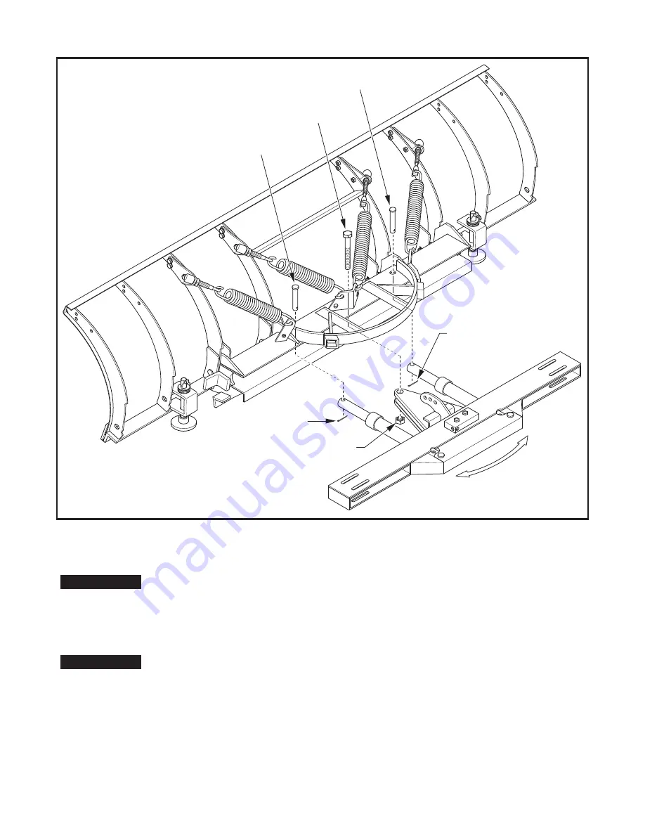
Figure 9. Mount A-Frame to Trip Frame
1" Nylon
Lock Nut
1" x 6" Bolt
Apply Grease
3/16" x 1-1/2"
Cotter Pin
3/16" x 1-1/2"
Cotter Pin
1" x 4" Clevis Pin
S
w
in
g
A-F
ram
e
L&
R
t
o
ins
e
r
t Pi
n
s
1" x 4" Clevis Pin
11.)
Locate and install the two Hydraulic Hoses (1TBP72) to each side of the By-Pass Relief Valve and to the
corresponding Ports on the Left and Right Angle Cylinders.
Do not
use Teflon Tape on the Hydraulic Fittings as it may contaminate the Hydraulic
System causing a malfunction. Use a high quality paste type thread sealant on all N.P.T.
fittings.
Due to the large number of variations in tractor hydraulic systems and fittings, two hoses
with 1/4" male NPT threads have been provided to connect between the tractor and
By-Pass Valve, but fittings and quick connectors have not. Most skid steer loaders
have extra lines which can be tied into. Some tractors have an auxillary valve that can be
used, or an optional valve kit can be purchased from Curtis. The last option is to connect
the lines from the loader tilt cylinders and tie them into the bypass block. Be sure to
connect before the T-Fitting that connects the left and right tilt cylinders. If using this
option the loader blade will need to be supported with Lift Chain provided. See Step 12
below.
12.)
Attach Lift Chain (1TBP30A) to A-Frame assembly with 5/16" Anchor Shackle (1TBP31).
IMPORTANT
IMPORTANT


