Curtis Front End Loader Blade (F.E.L.B.) Assembly Instructions (continued)
7.)
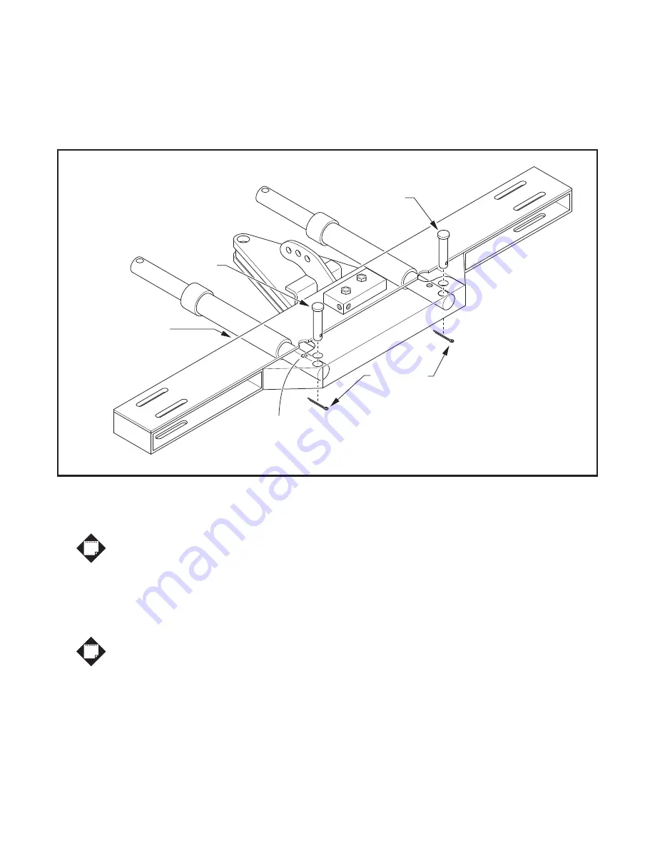
Locate both 10" Angle Cylinders (1TBP27) and mount one to each side of the A-Frame. The Angle Cylinders
will be inserted into the A-Frame at the front through the slots, with the Hydraulic Port facing up and visible
through the opening at the top of the A-Frame. Mount each Angle Cylinder to the A-Frame with a 1" x 3" Clevis
Pin (1TBP73) and secure each Clevis Pin with a 3/16" x 1-1/2" Cotter Pin (1TBP24). Refer to Figure 8.
8.)
Lift the A-Frame above the Trip Frame, and insert the A-frame and Angle Cylinders into the Trip Frame.
Apply grease to the 1"-8 x 6" Gr.5 Center Bolt (1TBP25) and insert through the Trip Frame and A-Frame.
Secure the Center Bolt with a 1" Nylon Lock Nut (1TBP26). Refer to Figure 9.
Do not over tighten the Nylon Lock Nut, the A-Frame must pivot freely.
9.)
Swing A-Frame to Left or Right and align hole in Angle Cylinder Ram with the corresponding hole in Trip
Frame. Install (1) 1" x 4" Clevis Pin (1TBP23) through Trip Frame and Angle Cylinder Ram.
Secure Clevis Pin with (1) 3/16" x 1-1/2" Cotter Pin (1TBP24). Swing A-Frame to opposite side and
repeat alignment and pinning procedure. Swing A-Frame back to the center.
It may be necessary to extend the Angle Cylinder Piston Rod 1-2" to make
the connection to the Trip Frame. To do this, insert a long pin or ratchet handle
through the Piston Rod and work the piston Rod side to side while pushing downward.
10.)
Return the A-Frame to the center position after the Angle Cylinders are secured to the Moldboard.
Using the A-Frame as a lever, grasp the A-Frame by the cross-brace and pull back, raising the Moldboard
to a vertical position.
Figure 8. Mount Angle Cylinders to A-Frame
1" x 3"
Clevis Pin
1" x 3"
Clevis Pin
Angle Cylinders are
inserted into slots in
the front of A-Frame
3/16" x 1-1/2"
Cotter Pins
install from
below
Hose Ports up
NOTE
NOTE
7 of 14


