07/2009 - Art. Nr. 13 022 182A
14
Commissioning
Gas operation
Program sequence test
Setting the burner
Testing the burner program
sequence before initial gas release
• Close the manual valve located
upstream of the gas train.
• Bridge the gas pressure switch
(terminals 2 and 3), if necessary, if
there is insufficient gas pressure
upstream of the gas train; Disconnect
the burner from the power supply first.
• Check that fuel selection switch
S10
is
in the
GAS
position.
• Start the burner by switching on the
heat generator and test the program
sequence.
• The blower starts after a delay,
depending on the control and safety
unit setting.
• Pre-ventilation time (54 s)
• Pre-ignition time (3 s)
• Magnetic valves open
• Safety time (3 s)
• Safety shutdown at the end of the
safety time with locking of the control
and safety unit(malfunction lamp lit).
• Cut the power to the burner by
disconnecting the electrical
connection and remove the wire
jumper for the gas pressure switch if
necessary.
• Reconnect the electrical connection.
• Unlock the control unit.
• Start the burner.
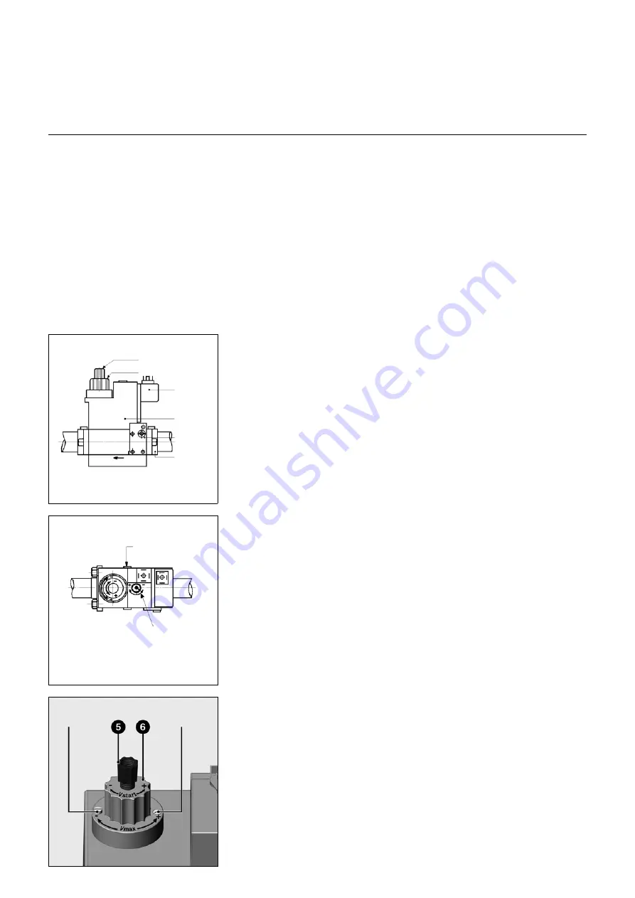
Ignition throughput setting -
incremental advance setting
• Unscrew protective cap
5
and turn it
through 180° to use it as an
adjustment tool.
• Turn the adjustment spindle to the
minimum position, then turn it back
towards the plus symbol to the centre
position (approximately 3 half turns).
The initial gas flow is now set to around
half open.
• To achieve smooth starting, the initial
gas flow should be adapted to the
boiler pressure conditions.
Full load flow adjustment
• Loosen the locking screw until rotary
knob
6
becomes adjustable. Do not
loosen the sealed screw on the
opposite side.
• Reduce the main flow by turning knob
6
clockwise or increase it by turning it
anticlockwise. The total path to adjust
from minimum to maximum flow is
approximately 4.5 turns.
• Retighten the locking screw after the
adjustment has been made.
Pressure regulator setting
The adjusting screw has a path of 60
turns for adjusting the output pressure.
Three turns clockwise or anticlockwise
increases or reduces pressure by 1
mbar respectively.
At commissioning:
• Turn the screw through at least 10
turns clockwise (+)
• Then fine tune the adjustment (more or
less pressure)
• Check the gas pressure either at the
multiblock
pBr
(M4) or the gas
collector measurement nipple Ø9.
Optimising combustion values
Optimum combustion values can be
achieved by adjusting the position of the
turbulator (dimension
Y
) if necessary.
Doing this can have an effect on starting
characteristics, pulsation and
combustion values. Any reduction in
scale value
Y
increases the CO
2
value.
However, starting characteristics
become harsher. Compensate for the
change in airflow if necessary by
adjusting the air flap position.
Precautions: To avoid condensation
forming, observe the minimum
required exhaust gas temperature
specified by the boiler manufacturer
and comply with the exhaust gas duct
requirements.
Locking
screw
Painted
screw
pBr
Pressure
regulator
setting
S 50 = from 4 to 50
mbar
Pressure
switch
Coil
Access to the
filter
Connecting
flanges
Incremental advance
setting
Flow setting
Содержание NC12 B117
Страница 42: ...07 2009 Art Nr 13 022 182A 42 ...
Страница 43: ...07 2009 Art Nr 13 022 182A 43 ...


