
Cubix Corporation
2800 Lockheed Way
Carson City, NV 89706-
0713 ● Page 8
Sales 800.829.0550
http://www.cubix.com
xprm8g3-825urp24-20181001
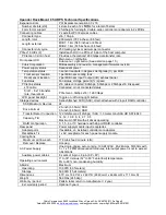
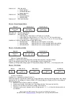
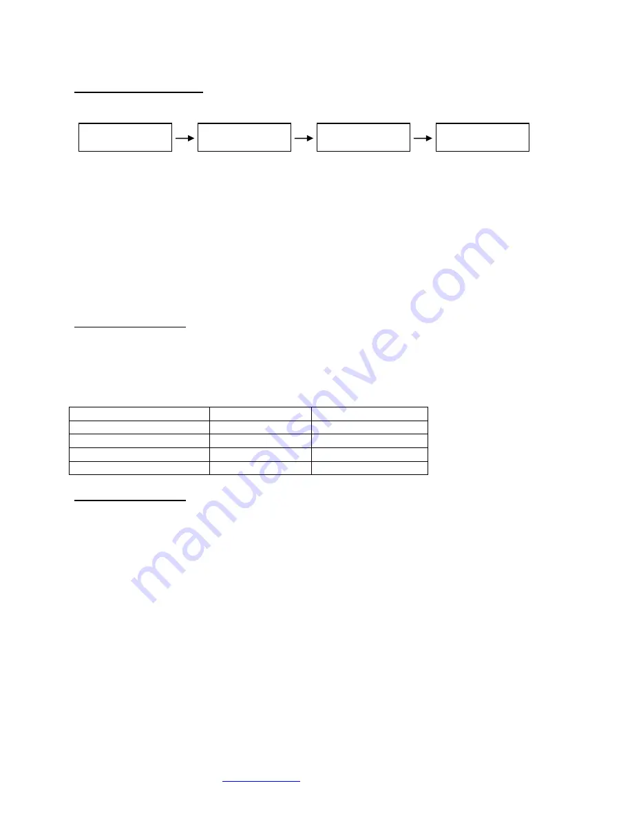
Menu 5: PCIe Link Status
Menu
Sub-menu
Sub-menu
Sub-menu
Menu 5: PCIe Link Status
Sub-Menu 1: Indicates x16 PCIe cable installation status
•
Connected
x16 cable is properly connected to the HIC
•
NOT-Connected
x16 cable is not properly connected to the HIC
Sub-Menu 2: x16 PCIe cable link speed and link width. Speed and width depend on the host capability.
•
Speed: 8.0Gb/s, 5.0Gb/s or 2.5Gb/s
•
Width: x1, x2, x4, x8, x
16 and “NO Link” when the host did not successfully link or Xpander is
in standby power.
Sub-Menu 3-6: Link speed and link width for slots 1-4.
•
Speed: 2.5Gb/s, 5.0Gb/s or 8.0Gb/s
•
Slot 1-2 width: x1, x2, x4, x
8, and “NO Link” when the slot is empty, unsuccessful link, or
Xpander is in standby power.
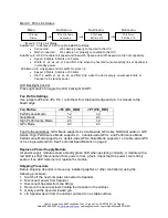
LCD Backlight Control
Press right switch to toggle the LCD backlight On/Off.
Fan Profile Settings
Use jumpers JP8 and JP2. Pin 1 is furthest from the board edge and pin 3 is closest to the
board edge.
Fan Profile
JP8 (PIC_RB0)
JP7 (PIC_RB1)
Performance Mode
1-2
1-2
Quiet Mode
1-2
2-3
High Performance Mode
2-3
1-2
GPU Mode
2-3
2-3
Fan Profile Guidelines. GPU Mode supports 4 x double-wide GPUs like NVIDIA Quadro or GTX
Series. High-Performance Mode supports 2
– 3 double-wide GPUs. and Performance Mode
Performance Mode supports 2 x double-wide GPUs. Quiet Mode supports 1 x double-wide GPU
or 4 x single-wide GPUs. See Technical Specifications on page 2.
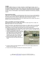
Replace a Power Supply Module
All power supply modules show a steady green LED when operating normally. A module with a
red LED is either disconnected from power or has a fault. Check that the power cord is firmly
seated. If an LED remains red, replace the module.
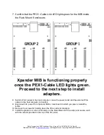
Shipping Procedure
Before shipping Xpander, remove any installed graphics or other controller(s) using the
following procedure:
1. Switch off the host computer connected to Xpander.
2. Disconnect power from Xpander.
3. Disconnect Xpander from the HIC(s).
4. Remove the secure screws holding the Xpander in the cabinet.
5. Gently pull the Xpander toward you.
6. Lift Xpander down from the cabinet and set it on a stable surface.
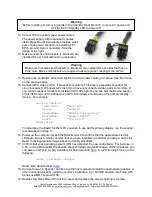
PCIe Link
Status
c
PCIe X16 Cable
Connected
c
PCIe Cable
8.0Gb/s X16
c
PCIe Slot n
8.0Gb/s X16
c


