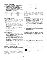
27
•
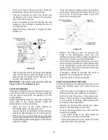
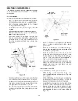
Loosen the two hex jam nuts and turn them away
from the backside of the front hanger rod bracket.
•
If the front of the deck was too low, turn the hex
flange nuts on the ends of the front hanger rod
clockwise to raise the front of the deck. See
Figure 29.
•
If the front of the deck was too high, turn the hex
flange nuts counterclockwise to lower the front of
the deck.
IMPORTANT: The deck front hanger rod should
be at the front of the slots of the front deck
bracket. If one side of the rod is not at the front of
its slot, turn the hex flange nut on the that side
until rod just touches the front of the slot. Then
re-measure and re-adjust the front hanger rod as
necessary.
•
When the correct pitch of the deck is acquired,
tighten the hex jam nuts against the front hanger
rod bracket.
ADJUSTING THE GAUGE WHEELS
The cutting height of the mower deck can be set in
any of six height settings using the deck lift handle of
the tractor. The deck heights range from 1-1/2 inches
to 4 inches. The deck gauge wheel position should be
approximately 1/4 to 1/2 inch above the ground when
the deck is set in the desired height setting.
WARNING: Keep hands and feet away
from the discharge opening of the
cutting deck.
NOTE: The deck wheels are an anti-scalp feature of
the deck and are not designed to support the weight of
the cutting deck.
Using the lift handle, set the deck in the desired
height setting, then check the gauge wheel and if
necessary adjust as follows.
•
With the deck set at the desired height, visually
check the distance between the gauge wheels
and the ground. If the gauge wheels are near or
touching the ground, they should be raised. If the
gauge wheels are too high, they should be
lowered.
•
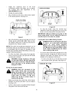
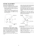
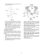
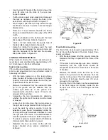
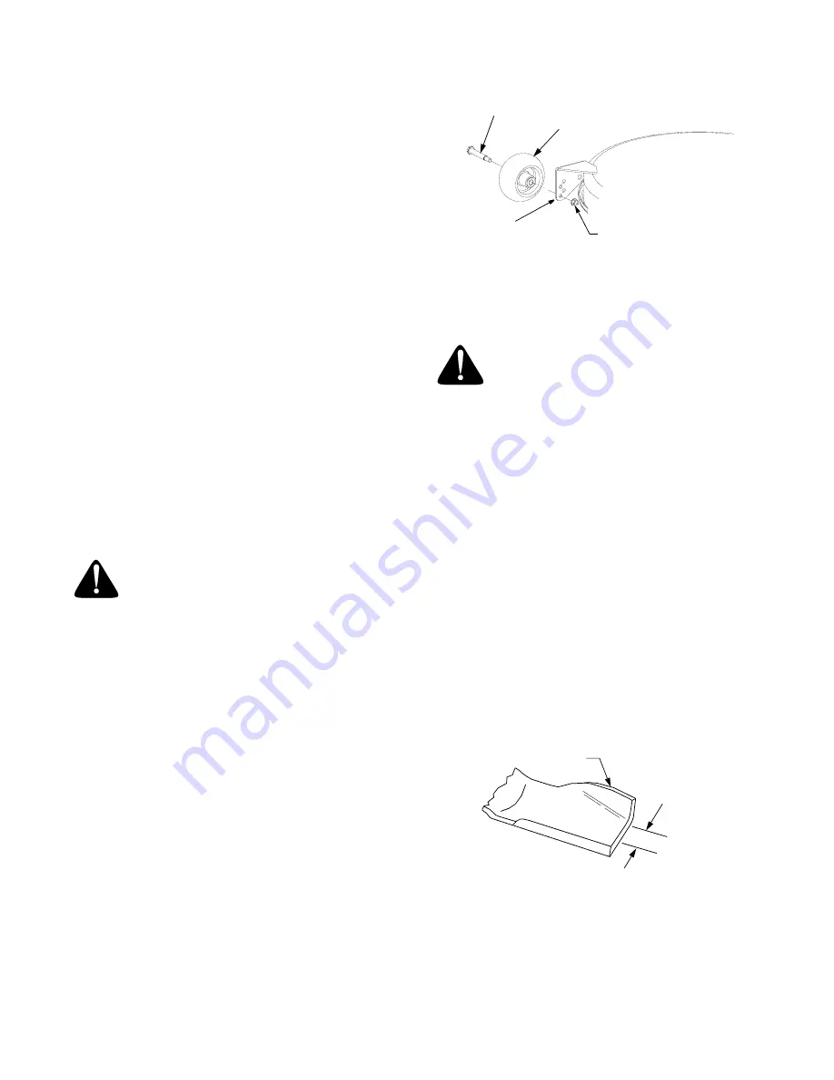
Remove the lock nut securing one of the gauge
wheel shoulder screws to the deck. Remove the
gauge wheel and shoulder screw. See Figure 30.
•
Insert the shoulder screw in the one of four index
holes that will give the gauge wheel a 1/4 to 1/2
inch clearance with the ground.
•
Note the index hole of the just adjusted wheel,
and adjust the other gauge wheel into the
respective index hole on the other side of the
deck.
Figure 30
DECK MAINTENANCE
Cleaning And Blade Care
WARNING: Before performing any main-
tenance, place the PTO switch in the
“OFF” position, engage the parking
brake lever, turn the ignition key to the
“OFF” position and remove the key from
the switch. When servicing the mower
deck, be careful not to cut yourself on
the sharpened blades.
Clean the underside of the mower deck at the end of
the mowing season or when buildup of cut material
on the underside is noticed.
Once a month remove the belt covers to remove any
accumulation of grass clippings from around the
spindle pulleys and V-belt. Clean more often when
mowing tall, dry grass.
The cutting blades must be kept sharp at all times.
Sharpen the cutting edges of the blades evenly so
that the blades remain balanced and the same angle
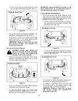
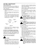
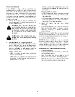
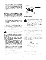
of sharpness is maintained. If the cutting edge of a
blade has been sharpened to within 5/8 inch of the
wind wing radius, it is recommended that new blades
be installed. See Figure 31.
Figure 31
The blades may be removed as follows.
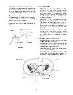
•
Remove the deck from beneath the tractor, (refer
to Deck Removal
on page 25) then gently flip the
deck over to expose its underside.
Lock
Nut
Rear
Wheel
Gauge
Shoulder
Screw
Gauge
Wheel
Bracket
Wind
Wing
5/8" From
Radius

