


16
S
ection
5 — P
roduct
c
are
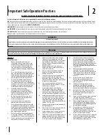
Checking & Adding Engine Coolant
CAUTION
Do not remove radiator cap while coolant is hot . When cool
slowly rotate to the first stop and allow sufficient time for
excess pressure to escape removing the cap completely.
1.
Park the vehicle on a flat surface, remove
the hood panel, set the parking brake, and
shut off the engine.
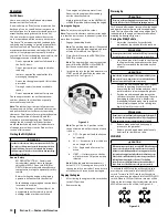
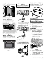
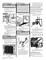
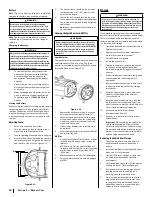
2.
Check to see that the coolant level is
between the FULL (a) and LOW (b) marks of
recovery tank (c). See Figure 5-12.
(a)
(b)
(c)
Figure 5-12
3.
When the coolant level drops due to
evaporation, add water only up to the FULL (a)
level. In case of leakage add anti-freeze and
water in the specified mixing ratio up to the
FULL (a) level. (See Flushing and Changing
Coolant section).
•
Use clean fresh water and anti-freeze
to fill the recovery tank.
•
If water should leak, consult your
local Dealer.
Note:
If the radiator cap has to be removed,
follow the cautions above and securely
retighten the cap.
Cleaning the Radiator Screen
CAUTION
Be sure to stop the engine before removing the screen.
Note:
Radiator screen must be cleaned from debris
to prevent engine from overheating
1.
Park the utility vehicle on a flat surface.
2.
Remove the radiator cover.
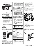
3.
Detach the screen and clean the radiator and
radiator screen and radiator fins of all debris.
See Figure 5-13.
Figure 5-13
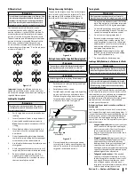
Checking & Adding Brake Fluid
CAUTION
Never operate the vehicle if the brake fluid is below the
minimum mark. Use only DOT3 from a sealed container.
Other types of brake fluid may ruin synthetic resin or rubber
installed in brake system components and may cause brake
failure. Avoid contamination of the brake fluid thoroughly
clean around the filler cap before removing. Do not open
the brake fluid reservoir cap unless absolutely necessary.
Use extreme care when filling the reservoir. If brake fluid
spill on coolant hose, wash off with water immediately, as
brake fluid quickly ruins synthetic resin or rubber hoses.
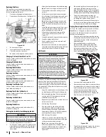
1.
Check to see that the brake fluid level on the
brake fluid reservoir (a) is up to the MIN (b)
level. See Figure 5-14.
(a)
(c)
(b)
Figure 5-14
2.
If it is below the MIN (b) level add brake
fluid, but do not exceed the MAX (c) level.
Checking the Brake Pedal
WARNING
Stop the engine and chock the wheels before checking
brake pedal.
Inspect the brake pedals for free play (a), pedal
stroke (b) and smooth operation. Refer to Figure
5-15.
(a)
(b)
Figure 5-15
1.
Release the parking brake.
2.
Step on the pedal and measure the free
play (a). There should be between .3” and
.5” (7-14 mm) of free play (a). If the free
play (a) measurement is outside of these
specifications, see an authorized service
dealer to have the brake adjusted.
3.
Step on the pedal and measure the stroke
(b). There should be less than 4.7” (120 mm)
of stroke (b). If the measurement is outside
of these specifications, see an authorized
service dealer to have the brake adjusted.
Checking & Adjusting the Parking Brake
Pull the parking brake to apply the brakes with
the key switch in the ON position and the parking
brake indicator should come on. To release the
parking brake, depress the parking pedal. Make
sure the parking brake warning lamp on the
display goes off when parking brake is OFF.
If the parking brake is in need of adjustment,
proceed as follows:
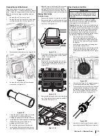
1.
Locate the parking brake adjustment nut
near the engine. See Figure 5-16.
(a)
(b)
Figure 5-16
2.
Loosen the lock nut (a) and then tighten the
bolt (b) to adjust the parking brake. Turn
the bolt until it touches, then back it off a
1/4-turn. See Figure 5-16.
If there is play in the parking brake handle there is
a secondary adjustment that can be performed.
1.
Look inside the driver’s side wheel well and
locate the adjustment point. Slide back the
rubber cover (a) on the adjustment nuts (b).
See Figure 5-17.
(a)
(b)
Figure 5-17
2.
Adjust the parking brake handle nuts (b)
until the free play in the handle is gone. See
Figure 5-17.
Checking & Adjusting the Shift Lever
If the shifter and the display image on the
instrument cluster do not match or the utility
vehicle is not shifting, a shift cable adjustment can
be performed.
1.
Remove the hood and the interior hood panel.
Содержание 550 2017
Страница 23: ...Notes 7 23...
Страница 24: ...24 Section 7 Notes...
Страница 25: ...25 Section 7 Notes...


