CANdle U
ser’s Guide
www.ctr-electronics.com 1/17/2022
Cross The Road Electronics Page 9 1/17/2022
2. Wiring
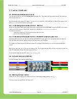
Due to the sealed nature of the CANdle, all wires leads are pre-installed. Because of this, customers can use whatever
connector solution is required for the application.
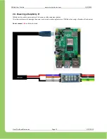
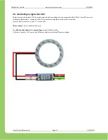
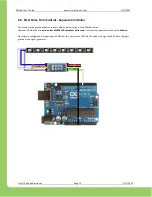
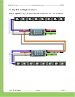
The wiring details will be determined by the desired use case of the CANdle. As a result this section documents several wiring
diagrams for each use-case.
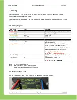
2.1. Wiring Diagram
Color of wire
Signal
Description
Inputs to CANdle
Red (18 AWG)
+V
IN
The supply input voltage (6 V
–
28 V, typically 12 V)
Black (18 AWG)
-V
IN
The supply ground (0 V)
Yellow (22 AWG)
CANH
(Note 1)
CAN Bus High
Green (22 AWG)
CANL
(Note 2)
CAN Bus Low
Outputs from CANdle
Blue (18 AWG)
5V
OUT
Regulated 5V for powering 5V addressable LEDs or 5V
development boards.
Orange (18 AWG)
+V
OUT
Provides voltage to LEDs that are rated for supply
voltage. This can be modulated via software.
A common use case is to power CANdle with 12V lead
acid battery, and use +V
OUT
to power 12V LEDs.
Use
+V
OUT
to
power 12V LED strips.
(Note 3)
Do
not
use
+V
IN
to
power 12V LED strips.
(Note 3)
White (18 AWG)
D
OUT
WS2812B compliant signal for individually addressable
LEDs.
Gray (18 AWG)
-V
OUT
Ground reference for all outputs.
Do
not
use -V
IN
to sink load currents.
Note 1:
Both
CANH wires are electrically common.
Note 2
:
Both CANL wires are electrically common.
Note 3
:
CANdle safely disables
+V
OUT
and
5V
OUT
during fault conditions.
Therefore, these must be used to power outputs for safe operation.
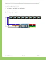
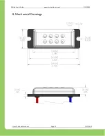
2.2. Enclosure Wire labels
Wire leads labels are available on the back of heatsink. This makes wiring the CANdle even easier.


