


-5-
Electrical Installation
Electrical Installation
Electrical Installation
Electrical Installation
Electrical Installation:::::
The CTD DMC70’s use two 1-1/2 H.P. single or three phase 3450 RPM, 60 HZ TEFC (totally enclosed fan cooled)
motors on a NEMA 56Z Frame. CTD uses a speed up drive so that the blade will run at approximately 3700 RPM.
Electrical installation should be performed by a qualified and certified electrician. A lock-out or disconnect switch
is located in front of the machine. It is a rotary switch to the left front of the machines. This disconnect switch is
used to shut off power to the machine and should be used whenever the blades are changed or at any time the
machine is serviced and the blades are exposed. A Dual Magnetic Starter, located inside the left side panel of the
machine protects the motor from overheating and will not allow the motor to restart itself after power outages or
undervoltage situations. The START button turns the motors “ON”. The STOP button turns the motors “OFF”.
Note: The STOP button must be pulled out before the START button will activate the motors.
Electrical Installation of Power to Starter by a Qualified Electrician:
Electrical Installation of Power to Starter by a Qualified Electrician:
Electrical Installation of Power to Starter by a Qualified Electrician:
Electrical Installation of Power to Starter by a Qualified Electrician:
Electrical Installation of Power to Starter by a Qualified Electrician:
All wiring from the motors to the starter has been completed and tested at the factory several times. The voltage
has been clearly tagged.
DO NOT CONNECT ANY VOLTAGE THAT IS DIFFERENT THAN THE TAGGED
VOLTAGE, AS THIS MAY CAUSE SEVERE DAMAGE AND DANGER.. CONSULT FACTORY IF ANY
CHANGES ARE NEEDED.
Bring incoming power lines to the left side using hard wire and dust proof connectors.
Attach incoming power lines through Floor Stand to the rotary disconnect switch. Connect to terminals 2 & 4
for single phase motors, and to terminals 2, 4 & 6 for three phase motors. Always ground the green wire.
(See wiring diagram on Page 6.)
Single Phase Motor Replacement:
Single Phase Motor Replacement:
Single Phase Motor Replacement:
Single Phase Motor Replacement:
Single Phase Motor Replacement:
Connect motor leads to T1 and T3 of overload relay for single phase motors. (See wiring diagram for single
phase motors on following page) Green ground wire must be grounded to enclosure. If using type “SO” wire
and plug, use a dust tight connector through Floor Stand and a grounded plug.
Be sure to check rotation. If a
change is necessary, open the motor box located on the motor, and switch the #8 and the #5 wires. This reverses
the rotation of a single phase motor. The blade must rotate down and to the rear on the underside of the blade
(see Diagram “D” on Page No. 4).
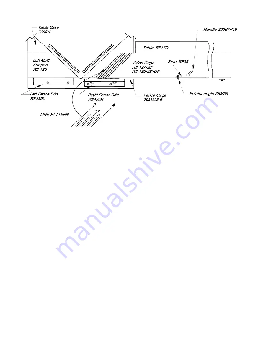
Vision Gage Diagram
The hinged front blade guard must be tightened down in place properly
The hinged front blade guard must be tightened down in place properly
The hinged front blade guard must be tightened down in place properly
The hinged front blade guard must be tightened down in place properly
The hinged front blade guard must be tightened down in place properly. . . . . An interlock switch, located on the
An interlock switch, located on the
An interlock switch, located on the
An interlock switch, located on the
An interlock switch, located on the
blade guard must be contacted or the motors will not start.
blade guard must be contacted or the motors will not start.
blade guard must be contacted or the motors will not start.
blade guard must be contacted or the motors will not start.
blade guard must be contacted or the motors will not start.
Содержание DMC70A
Страница 17: ...17 Right Side Shown Left Opposite...
Страница 18: ...18 DMC70 Top Plate Assembly Top View...
Страница 19: ...19 DMC70 Top Plate Assembly Bottom View...
Страница 20: ...20 DMC70 Plates Assembly Parts List...
Страница 21: ...21 DMC70 Gage Table Assembly...
Страница 22: ...22 DMC70 Floor Stand Assembly...
Страница 23: ...23 DMC70 Floor Stand Parts List...


