


26
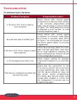
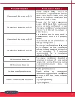
Problem Description
Recommended Actions
4-20 mA or 0-5/10
V
dc
output is
non-functional
Check status LED; ensure signal
conditioner is in Normal mode . Ensure
it was correctly programmed and
make sure all wiring is correct . Refer
to Figure 1 for wiring diagram . Use the
configurator’s error reporter to read
potential hardware issues .
No waveform data from BNC jack
Check status LED; ensure signal
conditioner is in Normal mode . Make
sure sensor is properly wired . Refer
to Figure 1 for wiring diagram . Ensure
the sensor power option is correctly
programmed .
4-20 mA or 0-5/10
V
dc
output is lower
than expected
Check filter settings . Make sure low-
pass and high-pass filters have been
set to range capable of capturing the
expected frequencies . Ensure the rest
of the configuration is correct .
4-20 mA signal is less than 2 mA
Check output cabling for damage .
Ensure load resistance is no more than
1 kΩ.
Filter data or configuration profile did
not send correctly
Ensure that the connection to the
PC is secure and did not come loose
during programming . Also make sure
that the signal conditioner does not
lose power during programming .
LED status light should remain solid
orange while plugged in . Check that
the configuration is correct and try
programming again .
Troubleshooting
Troubleshooting the Hardware


