CTC Union SC310 Series Скачать руководство пользователя страница 13

13

In the configuration tab are the configuration settings for the unit . The “Input 

Sensitivity” and “Input Units” dropdown menus define the sensor connected to 

the signal conditioner . Input Sensitivity refers to the sensor’s sensitivity, and the 

input unit refers to the sensor’s measurement type (g’s for acceleration, IPS and 

mm/s for velocity, and mils for displacement) . In Figure 3, the signal conditioner 

is configured to accept input from a 100 mV/g accelerometer . It is essential 

that this correctly matches the sensor type used to ensure proper scaling and 

accurate calculations . The software will allow you to use combinations of input 

sensitivity and input units that do not currently exist as sensors . If you do this, 

the software will alert you that the “Part number is invalid or the software is out 

of date . Config can still be applied” and produce a part number with a space in it . 
The “IEPE Power” dropdown menu controls whether or not the built-in IEPE 

supply on the device is enabled or disabled . In Figure 3, the IEPE power supply 

is configured to “ENABLED,” so once configured and plugged in, the signal 

conditioner will supply a constant 4 mA to the sensor .  The sensor input and thus 

settings described above are shared by both channels . Below, the “IEPE Power” 

dropdown menu is where each channel’s scaling settings are configured . For the 

SC310 series, only Channel 1 will be available to edit .
“Full-Scale Range” corresponds to the dynamic range of the measurement and, 

combined with “Output Units,” make up the scaling for the output control signal . 

The maximum selectable full-scale range is dependent on the sensor sensitivity . 

For more information, please visit 

https://documents.ctconline.com/archive/full-

scale-range-limitations

 . The output unit selections are the same as the input unit 

selections and depend on the sensor type . The output unit can either be straight 

through or integrated . In a straight-through configuration, the output unit matches 

the sensor input unit (e .g ., g’s in and g’s out) . In an integrated configuration, the 

output is integrated and then measured (e .g ., an accelerometer signal in g’s can 

be integrated to measure velocity in either IPS or mm/s) . Conversion can also 

take place between mm/s and IPS . The “Measurement Type” describes how the 

signal conditioner measures the sensor signal for scaling calculations . This can 

be either peak, peak to peak, or RMS, peak hold . 
For example, the input sensor in Figure 3 is 100 mV/g, the full-scale range is 

0-2 with a unit of g’s, and the measurement type is peak . Therefore, a midscale 

condition will occur when the sensor outputs a signal corresponding to 1 g peak 

(halfway between 0 g and 2 g) . If the measurement type were RMS instead, a 

mid-scale condition would occur if the RMS of the sensor signal was equal to 1 

g (a peak value of 1 .414 g) . If the signal was integrated and the output unit was 

IPS, a mid-scale condition would occur if the sensor were outputting a signal 

corresponding to 1 IPS after integration .

Содержание SC310 Series

Страница 1: ...SC310 Series Signal Conditioner SC310 Series Signal Conditioner Product Manual Product Manual...

Страница 2: ...ion 3 Installation 4 Signal Conditioner Configuration 6 Operation 16 Verifying Driver Support for Configuration 20 Troubleshooting 24 Software End User Agreement 28 Maintenance 38 Warranty and Return...

Страница 3: ...emperature sensor input voltage SC310 Series Overview The SC310 signal conditioner is a DIN rail mountable component used in continuous machinery monitoring applications It provides signal conditionin...

Страница 4: ...ctrical Connections 1 2 3 4 9 10 11 12 5 6 7 8 13 14 15 16 Temperature Output Temperature Output Dynamic Output Channel 1 Output Channel 1 Output CAN High CAN Low Dynamic Output Power In Power In Temp...

Страница 5: ...rminals 11 and 12 for channel one s 4 20 mA signal proportional to the vibration level 4 Connect output device to terminals 1 and 2 to obtain the 4 20 mA signal representative of temperature level 5 T...

Страница 6: ...n signal conductor wire which will then be run to a separate SC300 on terminal 13 The black common conductor will be run to one of the signal conditioners at terminal 14 then must be daisy chained to...

Страница 7: ...pplication files log files and database records Installing the Configuration Software 1 Log into your account on the CTC website a On the resulting page scroll down to the information panel and click...

Страница 8: ...may pop up asking about compressed folders Click Extract all 4 Double click the exe file located in the folder to launch the installer a Windows security might attempt to block the installer on launch...

Страница 9: ...tion for the program files to be installed If a different location is preferred click Browse and set the new destination Click Next 8 By default the program will add a launch button to the Windows Sta...

Страница 10: ...to include either a desktop icon or a Windows Start Menu launcher If neither of these options were included during installation it is still possible to launch the software by typing Signal Conditione...

Страница 11: ...currently discouraged to plug multiple devices in at the same time due to a limitation of the USB serial drivers that cause the devices to lock up if any two USB COM ports read or write at the same ti...

Страница 12: ...d configuration values The Part Number text box will also change the selected configuration values if a part number is typed or pasted into the box The Serial Number box will display the serial number...

Страница 13: ...le to edit Full Scale Range corresponds to the dynamic range of the measurement and combined with Output Units make up the scaling for the output control signal The maximum selectable full scale range...

Страница 14: ...it up the output units such as integrating for velocity on channel one and monitoring channel two for acceleration The Default Configuration button will load all dropdown menus with the standard ISO c...

Страница 15: ...by clicking View Errors If errors are present on the device View Errors will read them and display information about the error s for corrective action Any errors that appear may be cleared from the d...

Страница 16: ...e in the top menu will allow the user to select an option to view previous configurations Selecting this option will open the computer s default text file viewer with a log containing the date time se...

Страница 17: ...es the need for any adjustments to the analog output Indicators The LED on the front of the signal conditioner will indicate the status of the signal conditioner State 1 Normal Operation LED is solid...

Страница 18: ...ve been caused due to physical damage or misuse Processing will be disabled in this case Communication with the configurator may or may not work depending on the root cause but should be attempted as...

Страница 19: ...voltage from the temperature sensor to an exact 4 20 mA value This functionality is only applicable with a CTC TA200 Series dual output sensor Output mA Temperature C Signal Conditioner 4 20mA Tempera...

Страница 20: ...turned off Although the BNC connector circuitry offers short circuit protection and can safely sink the current long term degradation may occur due to increased power dissipation depending on the magn...

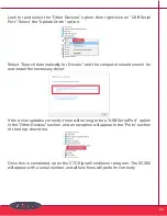
Страница 21: ...k the USB connection to make sure it is secure Confirm that the LED indicator on the SC300 unit is lit up with a solid orange light LED will blink when first plugged in and should then turn solid oran...

Страница 22: ...uld search for and install the necessary driver If the driver updates correctly there will no longer be a USB Serial Port option in the Other Devices section and a new option will appear in the Ports...

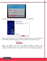
Страница 23: ...he first step is to go to the link below https ftdichip com drivers vcp drivers Scroll down to the download link section and select the setup executable option on the left side Save the file it will b...

Страница 24: ...Manager If all is correct USB Serial Port COMX will be displayed in the Ports section of the drop down menu When this appears open the CTC Signal Conditioner program The SC300 will appear with a seria...

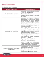
Страница 25: ...fying Driver Support for Configuration page The device may take as long 40 seconds for the software to recognize the signal conditioner This will be especially true with signal conditioners older than...

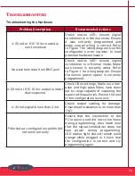
Страница 26: ...med 4 20 mA or 0 5 10 Vdc output is lower than expected Check filter settings Make sure low pass and high pass filters have been set to range capable of capturing the expected frequencies Ensure the r...

Страница 27: ...um for voltage configurations For current configurations load must be configured so that compliance voltage voltage powering the device is not exceeded 1k maximum recommended for a compliance voltage...

Страница 28: ...configuring CH1 Error configuring CH2 Error configuring CH1 CRC Error configuring CH2 CRC Once installed and connected to an online system PLC DCS SCADA the values that the system receives do not mat...

Страница 29: ...L NUMBER FROM THE SIGNAL CONDITIONER IN THE BOX AND CLICKING ACCEPT YOU A ACCEPT THIS AGREEMENT AND AGREE THAT LICENSEE IS LEGALLY BOUND BY ITS TERMS AND B REPRESENT AND WARRANT THAT YOU HAVE THE RIGH...

Страница 30: ...in this Agreement CTC hereby grants to Licensee a non exclusive non transferable non sublicensable limited license in the Territory during the Term to solely by and through its Authorized Users a down...

Страница 31: ...n any other programs e reverse engineer disassemble decompile decode or otherwise attempt to derive or gain access to the source code of the Software or any part thereof f remove delete alter or obscu...

Страница 32: ...this Agreement s provisions as applicable to such Authorized User s use of the Software and shall cause Authorized Users to comply with such provisions 6 Compliance Measures Licensee authorizes CTC t...

Страница 33: ...ffect until terminated as set forth herein the Term Licensee may terminate this Agreement by ceasing to use and destroying all copies of the Software and Documentation CTC may terminate this Agreement...

Страница 34: ...LICENSEE AS IS AND WITH ALL FAULTS AND DEFECTS WITHOUT WARRANTY OF ANY KIND TO THE MAXIMUM EXTENT PERMITTED UNDER APPLICABLE LAW CTC ON ITS OWN BEHALF AND ON BEHALF OF ITS AFFILIATES AND ITS AND THEIR...

Страница 35: ...Licensee except for information which is i already known by the Licensee ii becomes through no act or fault of the Licensee publicly known iii received by Licensee from a third party without a restri...

Страница 36: ...f its obligations under Section 9 or in the case of Licensee Sections 2 4 7 b 11 or 12 would cause the other Party irreparable harm for which monetary damages would not be an adequate remedy and agree...

Страница 37: ...effect and be binding upon the parties hereto f Section Headings The headings of the sections paragraphs and appendices herein are for the Parties convenient reference only and shall not define or lim...

Страница 38: ...written and comparable terms refer to printing typing and other means of reproducing words including electronic media in a visible form References to any agreement or contract are to that agreement or...

Страница 39: ...ver fail we will repair or replace it at no charge Refund All stock products can be returned for a 25 restocking fee if returned in new condition within 90 days of shipment Stock products qualify for...

Отзывы: