


FMUX03/V35
10
Chapter 3 – Operating Instructions
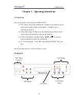
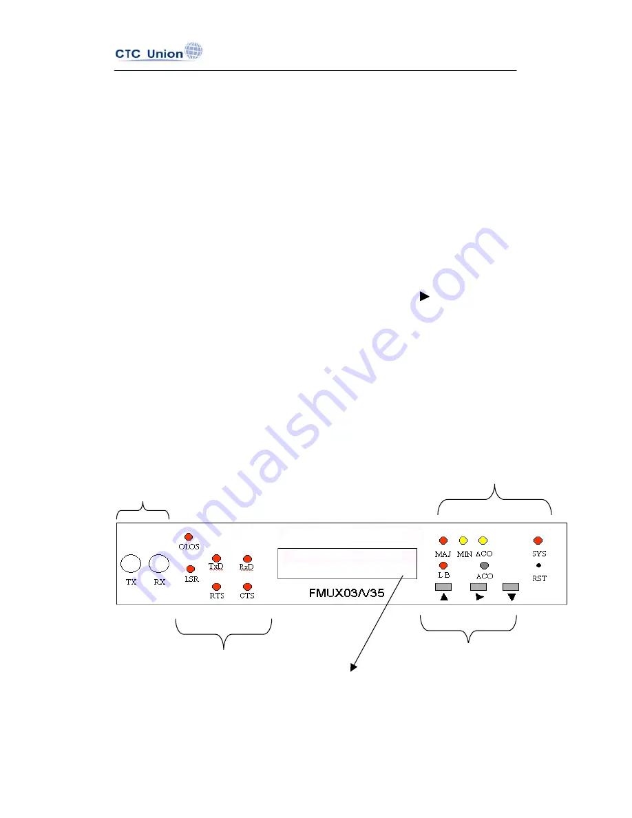
3-1 Front Panel
There are four parts to the front panel of FMUX03/V35:
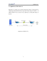
(1) Fiber Optics Connectors and Indicators: Notifies user of a problem such as
LOS (Loss of Signal) and Laser LED (LSR). Includes a pair of
input/output connector
(2) Alarm LED Display: Notifies users of a problem such as a Major Alarm
(MAJ), Minor Alarm (MIN), and System Alarm (SYS).
(3) LCD Control Buttons: The three buttons,
▲
,
▼
, and are used for
system configuration and for the loopback test.
(4) V.35 Port Status LED: Four LEDs, representing TXD, RXD, CTS, and
RTS.
Each of the LED indicators is described below in detail:
Front panel
Fiber Optics
Connector
LED Display
LED Display
LCD Control
Button
LCD Panel
Содержание FMUX03/V35
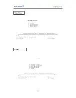
Страница 1: ......
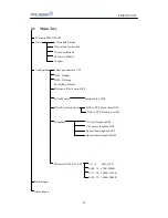
Страница 17: ...FMUX03 V35 17 Main Menu Profile ...
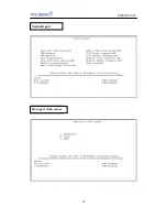
Страница 18: ...FMUX03 V35 18 Configuration Alarm Status Report ...
Страница 19: ...FMUX03 V35 19 Status Report Data port clock source ...
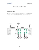
Страница 20: ...FMUX03 V35 20 Data port clock invert Loopback ...
Страница 21: ...FMUX03 V35 21 Data rate N 64K N 1 32 N 01 08 64K 512K ...
Страница 22: ...FMUX03 V35 22 N 09 16 576K 1024K N 17 24 1088K 1536K ...
Страница 23: ...FMUX03 V35 23 N 25 32 1600K 2048K ...


