

Disconnect the power supply before
beginning installation to prevent electric shock
or equipment damage.
All wiring must comply with local codes
and ordinances.
To wire and mount the thermostat:
1. Remove cover from thermostat base by
gripping the base in one hand. Use the
other hand to pull gently at the top or
bottom of the cover.
2. Carefully remove the protective packing.
3. Loosen the 4 screws holding the
thermostat to the sub-base, then separate
them. Refer to Figure 1.
4. Pull wires through opening near center
of sub-base and connect wires beneath
terminal screws (See figure 2-5 for typical
wiring for each application, Also refer
to the following subsections for special
system configurations).
5. Push excess wiring into wall and plug
hole with fire-resistant material (such as
fiberglass insulation) to prevent drafts
from affecting thermostat operation.
6. Position sub-base over hole in wall and
mark mounting locations. Use any existing
mounting holes if possible.
7. If the mounting screws will be going into
drywall only, then drill 3/16” mounting
holes for use with the included plastic
anchors.
8. Fasten sub-base loosely to wall with two
mounting screws. Place a level on the
raised, flat surface near the bottom of the
sub-base, adjust until level, then tighten
the mounting screws. (Refer to Figure 2.)
An incorrectly leveled thermostat
will cause the temperature control to
deviate from the setpoint.
ATTACH SUB-BASE TO WALL
Electric Heat Furnaces
(Single Transformer Systems only)
The sub-base, as supplied, may not operate
the fan correctly. If both the heating and the
cooling system must operate the fan relay,
remove the factory-installed jumper wire
from the
Y
terminal and connect it to the
A
terminal. The fan should now cycle when the
thermostat calls for either heat or cool.
Two-Transformer Systems
If two transformers are used, they must
be in phase. Failure to do so may result
in personal injury and/or property
damage.
NOTE:
Wire color does not indicate
polarity. Polarity is obtained from an
oscilloscope or voltmeter.
Remove jumper between RC and RH terminals
for two transformer systems.
Heat Pump Applications
This sub-base
WILL NOT
provide multi-
stage heating or cooling operation. For
single stage heat pump applications, install
a short jumper wire across terminals
W
and
Y
. If the old thermostat has a terminal that
is continuously energized, disconnect the
wire from the old thermostat’s terminal and
connect it
either
to the: 1)
B
terminal, if the
reversing valve is energized on a call for heat;
or
to the 2)
O
terminal, if the reversing valve is
energized on a call for cool. If the system heats
on a call for cool, or vice versa, this wire has
been connected to the wrong terminal.
NOTE: RH
and
RC
must be jumpered for
single transformer heat pump systems.
Special Application Terminals
The
B
and
O
terminals can provide
switching for special functions other than heat
pump operation. When the system switch is in
the
HEAT
position, the
B
terminal is energized.
When the system switch is in the
COOL
position, the
O
terminal is energized.
SPECIAL APPLICATIONS
1. Attach thermostat base to sub-base, being
sure that 4 captive screws are tightnened
snugly, since they serve as electrical
connections between thermostat and sub-
base.
2. Snap cover on thermostat and set switches
and temperature lever to desired setpoint
3. Turn on power to the system.
ATTACH THERMOSTAT TO SUB-BASE
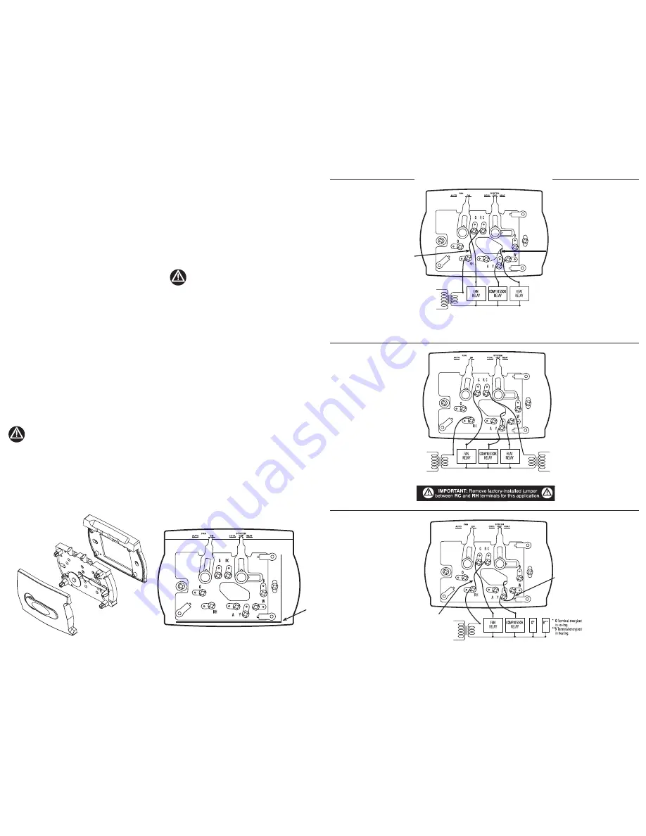
TYPICAL WIRING DIAGRAMS
LEVELING
SURFACES
FIG.2. THERMOSTAT SUB-BASE
FACTORY
INSTALLED
JUMPER
WIRE
YELLOW
JUMPER
FIG. 3. SINGLE TRANSFORMER H/C SYSTEM
For electric heat-fan to cycle with either heat or cool, move yellow jumper from Y terminal to A
terminal (see dotted line at terminal A in illustration.)
FIG. 5. SINGLE TRANSFORMER, SINGLE STAGE HEAT PUMP SYSTEM
Install jumper between W and Y terminals (see illustration.)
FIG. 1 ATTACH THERMOSTAT TO SUB-BASE
FIG. 4. TWO TRANSFORMER H/C SYSTEM
FIELD
INSTALLED
JUMPER
WIRE
FACTORY
INSTALLED
JUMPER WIRE
41630-01 4/22/2003
Cover
Thermostat
Subbase
pg. 2
pg. 3


