


Vector Sensor Reference Manual
123
Note - For successful communications, the baud rate of the Vector Sensor ports must
be set to match that of the data logging or monitoring device. The Vector Sensor
only supports an RS-232C serial port of the external device.
RTCM Data Output
To output only RTCM correction data from the internal SBAS or beacon correction source:
•
Turn off all NMEA and binary messages using the $JOFF<CR><LF> command
•
Turn RTCM on using the $JRTCM,1<CR><LF> command
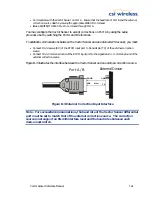
To establish communications between the Vector Sensor and an external GPS receiver, you must:
•
Connect Pin-2-transmit (TX) of Port A or B to the receive pin (RX) of the separate GPS receiver or
logging device.
•
Connect Pin-5-Common Ground of the serial port to the signal return or common ground of the
separate GPS receiver.
Figure B-2 illustrates the required interface between the Vector Sensor and device that receives
position information:
2 TX
RTCM
5 GND
GND
RX
Port A / B
External Device
Figure B-2 RTCM Data Output Interface
Note - For successful communications, the baud rate of the Vector Sensor port must
be set to match that of the separate GPS receiver. Additionally, you must interface
the Vector Sensor to an RS-232C serial port of the separate GPS receiver.
External Correction Input
In this operating mode, an external correction device inputs RTCM correction data through either
Vector Sensor Port A or B. In order to accomplish this, the Vector Sensor must be commanded
to use external corrections using the $JDIFF command.
To configure external correction input on Port B you must: