Crystal Vision ADDEC-310 Скачать руководство пользователя страница 27

Crystal Vision


Using the active front panel


ADDEC-310 User Manual R1.2 

26


10/12/2007 

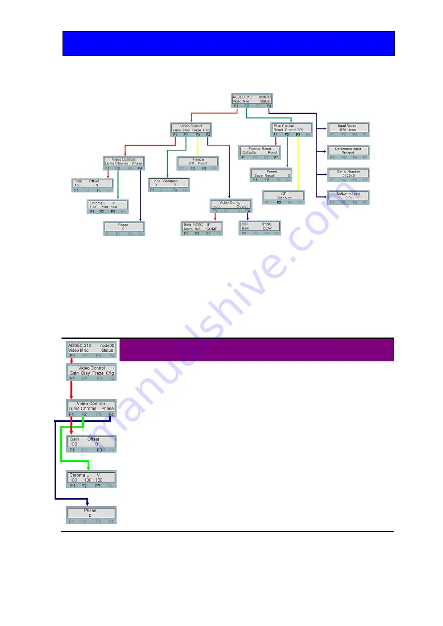
Active control panel menu tree 


Note: 

Function keys LEDs are illuminated when active. 

Video Configuration Menu 

The video configuration menu allows the user to tailor the various video functions of the 
ADDEC-310 to suit their specific application. 

Gains and offsets menu 


Menu 

Comment 


Gain and Offset 
menu 

Pressing function key F1 in the home menu selects the video control 
menus. Pressing function key F1 again gives access to the video gain 
and offset menus 


Video control 

Press a function key to make adjustments to the selected attribute. 


Lima gain and 
offset 

Rotate the shaft control to adjust either Luma gain or Offset once 
selected. Luma gain 80-120% in 1% steps. 
Offset 

±

 100mV in 6mV steps depending on input format. 


Chroma gain 
and UV 
component 
gains 

Rotate the shaft control to adjust the Chroma gain or U & V levels 
once selected. 
Adjustment 80-120% in 1% steps 


Phase / hue 
control 

Allows phase (NTSC Hue) correction in the analogue input video. 

±


90 deg in 1deg steps. 
Rotate the shaft control to adjust. 

Содержание ADDEC-310

Страница 1: ...n Technology Park Station Road East Whittlesford Cambridge CB22 4WL England E mail sales crystalvision tv Website www crystalvision tv Tel 44 0 1223 497049 Fax 44 0 1223 497059 ADDEC 310 Analogue to S...

Страница 2: ...dules and signal I O 6 Rear module connections with RM01 6 Rear module connections with RM23 7 Rear module connections with RM24 7 Rear module connections with RM25 8 Rear module connections with RM27...

Страница 3: ...e control panel menu tree 26 Video Configuration Menu 26 Miscellaneous menu 28 Status menu 29 5 Statesman 30 5 1 Statesman operation 30 Video properties 31 Presets 33 Gains 34 Factory Reset 35 6 Troub...

Страница 4: ...orrect frame rates plus any delays by taking its timing from the external analogue reference and will automatically synchronise sources between 0 and 2 fields An audio follow pulse is also produced wh...

Страница 5: ...s Synchroniser and Delay Modes There are two modes of operation Synchronisation and Delay In Synchronisation Mode the unit takes its timing from the analogue external reference and will automatically...

Страница 6: ...deo Data in the VBI vertical blanking interval of the analogue composite input can be blanked or passed NTSC J and NTSC M with or without 7 5 IRE set up is also selectable when receiving an NTSC forma...

Страница 7: ...ndigo desk top boxes both have a built in power supply and will house up to two single height modules Note For details of fitting rear connectors please refer to the appropriate frame manual Rear modu...

Страница 8: ...IN Component Y and G Composite YC Y and PAL NTSC input U B YCC IN SDI OUT Component U and B Composite YC C input Serial digital output link selectable SYNC IN Composite sync B B input Rear module conn...

Страница 9: ...nt Y and G Composite YC Y and PAL NTSC input Y G YCY CVBS IN LOOP Component Y and G Composite YC Y and PAL NTSC input looped on rear module U B YCC IN SDI OUT Component U and B Composite YC C input Se...

Страница 10: ...UT Serial digital output set PL9 SDI Module configuration The ADDEC 310 has eight user selectable jumper links which configure the Component U YC C Serial digital output the Component V SDI OUT the RG...

Страница 11: ...oved together as a pair Setting PL9 PL11 to external RGB syncs will disable the input format selection Loop or terminate the composite input The composite CVBS input may be terminated with 75 or left...

Страница 12: ...no a pin b pin c pin d pin e pin f pin 1 8 5 9 5 18 5 26 5 19 6 20 6 2 7 5 16 5 17 5 25 5 10 6 11 6 3 8 7 9 7 18 7 26 7 19 8 20 8 4 7 7 16 7 17 7 25 7 10 8 11 8 5 5 5 6 5 15 5 24 5 1 6 2 6 6 4 5 14 5...

Страница 13: ...e 4 are 26 way high density D Type male plugs and frame ground is pin 6 in each case and 5V 500mA is pin 15 on Remote 2 Note The 5V output is protected by self resetting thermal fuses which limit the...

Страница 14: ...8 1 9 1 18 1 26 1 19 2 20 2 2 7 1 16 1 17 1 25 1 10 2 11 2 Table shows pin number remote number Note Remote 1 26 way high density D Type female socket Frame ground is pin 2 and 5V 500mA is pin 1 Remo...

Страница 15: ...o controls 4 Not assigned Normally UP No customer functions 5 Video Gains and levels Allows the adjustment of the various video gains and levels 6 Engineering Allows access to factory reset defaults a...

Страница 16: ...tch levers in the UP position Scroll through and select desired menu by rotating the SELECT control The current value assigned will be displayed To change the assigned value rotate the ADJUST control...

Страница 17: ...lever 4 normally UP Gains offset and phase menu lever 5 ON DOWN all others OFF UP Engineering menu lever 6 ON DOWN all others OFF UP Not used lever 7 normally UP Note To save an adjustment toggle DIP...

Страница 18: ...ver 3 DOWN Selecting the video delay or offset This sets the number of lines or pixels to be delayed in Delay Mode or the vertical timing offset with respect to the reference input in Synchronisation...

Страница 19: ...ion synchronisation mode and delay line In Synchronisation mode the unit takes its timing from the analogue external reference and will automatically synchronise sources between 0 and 2 fields In Dela...

Страница 20: ...b 525 line format input where the PrPb components have been boosted by 1 333 can be selected Toggle DIL switch 1 to confirm new selection The following table shows the set up menu options Description...

Страница 21: ...ain nnn turn the ADJUST control to set the U gain to the desired level V gain Turn the SELECT control to display vGain nnn turn the ADJUST control to set the V gain to the desired level Black level Th...

Страница 22: ...n 6 F Not used N A Engineering settings There are two engineering settings Factory Default and Factory Reset DIL6 Factory Defaults This control when actioned will return all adjustable values to their...

Страница 23: ...Description Examples and comments ADJ funct 1 0 Default Default Dfalt Done N A 1 1 Reset Reset Reset Done N A 2 GPI enable Selecting ENABLE allows the recall of previously saved user configurations vi...

Страница 24: ...cleared prior to using the panel for the first time At power up the two line 20 character screen will display Crystal Vision followed by the firmware version number for the control panel All eight con...

Страница 25: ...ring power up updates the display Asterisk enters board rename menu from the Device menu F1 to F4 soft keys function assigned within each menu HOME moves the display to the home menu ENTER accept curr...

Страница 26: ...pdated immediately If necessary press CAL to update the display The ADDEC 310 menu structure At any time the main top level menu Home is obtained by pressing the HOME key From the home menu further se...

Страница 27: ...e video control menus Pressing function key F1 again gives access to the video gain and offset menus Video control Press a function key to make adjustments to the selected attribute Lima gain and offs...

Страница 28: ...Freeze and freeze mode Selecting F2 will force the output to frozen Toggle F3 to select Frame freeze Field 1 freeze or Field 2 freeze Configuration menu Menu Comment Configuration menu Pressing funct...

Страница 29: ...ult values for each parameter affected Parameter Default value Gains and levels 0 or 100 as applicable Synchronisation Mode Synchronisation Freeze Off Freeze Mode Field 1 Delay in lines 0 Delay in sam...

Страница 30: ...ecall of presets via GPIs can be enabled and disabled by toggling function switch F2 Status menu The status menu will give a quick overview of the board operation and engineering information Menu Comm...

Страница 31: ...communicates with each module in a frame through an active front panel A frame or frame pair must have an active panel fitted to allow for Statesman control For details on installing Statesman on your...

Страница 32: ...operties Presets controls gains and offsets and reset controls Video properties The video properties menu pane is made up of eight group boxes These group boxes allow the various formats and modes of...

Страница 33: ...be field 1 or field 2 Make the selection by checking the Frame Field 1 or Field 2 box then check the Freeze ON box to freeze the input NTSC format The 7 5 IRE set up present on the NTSC M format can b...

Страница 34: ...or recall any of the possible 16 presets that are available Storing and recalling Presets Saving and recalling presets The current board settings i e routing and delay can be saved in one of 16 locati...

Страница 35: ...to 100 U V Gain U slider varies Cb gain from 80 to 120 in 0 3 steps V slider varies Cr gain from 80 to 120 in 0 3 steps CAL button clears the current setting to 100 Black Level The black level can be...

Страница 36: ...ry Reset This control when actioned will return all adjustable values to their default value Note Any configuration stored as presets will also be erased This control can be used to restore a board fr...

Страница 37: ...and colours LED Colour Position Description Red Freeze Illuminates when output is frozen Green PSU Illuminates when the board is powered Green Ref Illuminates when an external reference is present Gre...

Страница 38: ...ength has not been exceeded Ensure that the external reference input is stable The video output is not synchronous with other station sources If the input analogue video is not synchronous with statio...

Страница 39: ...and less than 800ps broadband jitter from a stable 300mV Black and Burst reference Less than 500ps 1 kHz jitter in Delay Mode Low frequency jitter follows SDI input in Delay Mode only Timing Video tim...

Страница 40: ...ive front panel or Statesman PC control software GPI control GPI inputs 4 off 1 2 3 4 Recall presets 1 to 16 GPI outputs 5 Audio follow output pulse 6 Error Input absent Ref absent Not available at pr...

Отзывы: