


9- 3
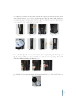
7. Insert the
1
/
4
inch blue tubing (Connected to POU Assembly) through the hole provided on the
Upper Support (Fig. 7-1) and then through the hole provided near the bottom of the back panel (Fig.
7-2)
8. Install the POU assembly on the reservoir, ensuring that it is correctly fitted (POU assembly
marked with the word FRONT) (Fig. 8-1 to Fig. 8-2)
9. Ensure the indicator is correctly set. The bar on the indicator will be to the front (Fig. 9-1) Work-
ing Position (Fig. 9-2) Locked (Reset) position (Fig. 9-3).
Figure 7-1 Figure 7-2
Figure 9-1 Figure 9-2 Figure 9-3
Figure 8-1 Figure 8-2
Содержание Everest Elite
Страница 1: ...Service Manual 100 115VAC EVEREST ELITE ...
Страница 21: ...Models Everest Elite Hot Cold 110V 5 3 ...