Crux Interfacing Solutions • 21541 Nordhoff Street, Unit C, Chatsworth, CA 91311
phone: (818) 609-9299 • fax: (818) 996-8188 • www.cruxinterfacing.com
rev.072419
5 of 13
R
INTERFACING SOLUTIONS
ACPBM-77Y
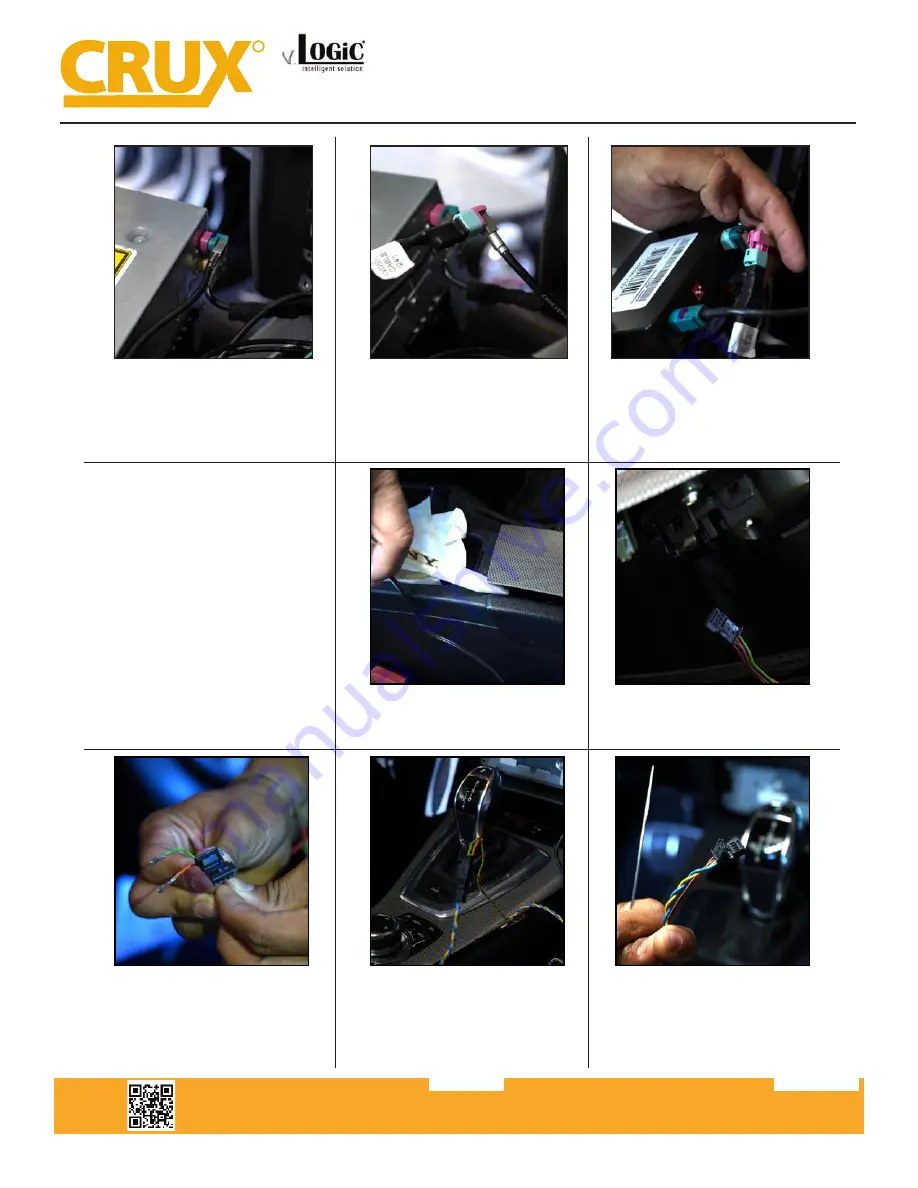
19. Connect the LVDS 2 cable in place
of the PINK LVDS factory cable.
20. Connect the factory PINK LVDS
cable to the male end of the LVDS 1
cable (CYAN colored connector).
21. Plug the otherside of the LVDS 1
cable into to the LVDS OUT port on
the ACPBM-77Y module. And plug the
otherside of the LVDS 2 cable into the
LVDS IN port on the same module.
22. If your vehicle is an F-series trim,
we will need to access the CAN data
from beneath the iDrive knob. This
only applys to you if you are using the
Power/CAN 2 Harness. If you are in
-
stalling on an E-series trim (Power/CAN
1) you can skip steps 23 - 28.
Refer to P. 7 for the wiring diagram for
the F-series if needed.
23. Carefully remove the center trim
using a trim removal tool to get under
-
neath the iDrive knob.
24. Your vehicle may have a 4-pin or
10-pin connector for the iDrive knob.
Remove the iDrive connector.
25. Using a pin removal tool, remove
the Green(CAN LO Pin 4) and Orange/
Green(CAN HI Pin 3) wires from the
iDrive connector.
Both 4 & 10 pin connectors have the same pin positions.
26. Insert the two pins (Orange/Green
--> Pin1 & Green --> Pin2) into the
empty 2-pin connector attatched to the
Yellow/Black & Blue/Black wires from
the Power/CAN 2 harness.
27. Insert the Yellow (CAN HI) --> Pin3
and Blue (CAN LO) ---> Pin4 wires into
the 4-pin iDrive connector (inplace
of the Green & Orange/Green wires
removed earlier).
Smart-Play Integration with Rear-View Camera Input for
E & F Series BMW Vehicles with CIC Infotainment Systems


