Page 12
Com-Tech 200/400/800/1600 Power Amplifiers
ducing the temperature of the air circulated through
the rack. If you intend to install air conditioning for your
amplifiers, you may want to use Section 7 to determine
the hourly thermal dissipation of your system.
3.3 Wiring
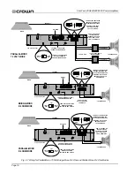
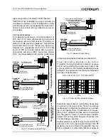
Figures 3.4 through 3.7 show common ways to install a
Com-Tech amplifier in a sound system. Input and out-
put terminals are located on the back panel. Please
use care when making connections, selecting signal
sources and controlling the output level. The load you
save may be your own! Crown assumes no liability for
damaged loads resulting from careless amplifier use
or deliberate overpowering.
CAUTION: Always disconnect the AC power and turn
the level controls off when making or breaking connec-
tions.
This is very important when loudspeakers are
connected because it reduces the chance of loud
blasts that can cause loudspeaker damage.
3.3.1 Mode of Operation
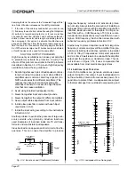
Proper wiring depends on how you configure your am-
plifier. First, each output channel can be indepen-
dently configured to drive step-down transformers in a
distributed “constant voltage” loudspeaker system
(70 volt mode) or loudspeakers that do not have step-
down transformers (8/4 ohm mode). Second, the am-
plifier can be configured for Dual, Bridge-Mono or
Parallel-Mono modes. Various combinations of these
modes are possible, so be sure to note any special
wiring requirements for the mode you will be using.
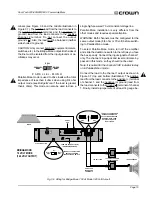
70
VOLT
8/4
OHM
7 0 V O L T
The 70 volt output mode is used to drive constant volt-
age lines without expensive step-up transformers.
Avoiding the use of step-up transformers not only
saves money, but it also eliminates the distortion and
insertion loss caused by this type of transformer.
Setting up 70 volt mode is easy. Turn off the amplifier,
then slide the recessed output mode switches to the
right (as you face the back panel).
If Bridge-Mono mode is used with 70 volt output, the
amplifier will actually deliver 140 volts (more informa-
tion is provided later in this section). To effectively use
this mode, you may need to cross-reference power rat-
ings for the step-down transformer taps using Crown’s
constant voltage computer (see Section 8.3).
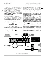
BLOWER
(OPTION 2)
BLOWER
(OPTION 1)
AIR
FLOW
FRONT
OF
RACK
DOOR
AIR
FLOW
EQUIPMENT
RACK
(SIDE VIEW)
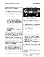
Mount the blower at the bottom of the rack so it blows
outside air into the space between the door and the
front of the amplifiers, pressurizing the “chimney” be-
hind the door (Figure 3.3, Option 1). The blower should
not blow air into or take air out of the space behind the
amplifiers. For racks without a front door, you can
evacuate the rack by mounting the blower at the top of
the rack, so that air blows out the back (Figure 3.3,
Option 2).
You can estimate the required air flow for a rack by
adding together the maximum required air flow ratings
of the individual units. The internal fan in a
Com-Tech
200 (if installed), 400 and 800 can move up to 35 cu-
bic feet (1 cubic meter) of air per minute, while the in-
ternal fan in a
Com-Tech 1600 can move up to 65
cubic feet (1.8 cubic meters) per minute. If you
mounted one of each
Com-Tech model in a rack,
worst-case conditions would require 170 cubic feet
(4.7 cubic meters) of air flow through the rack every
minute (3 x 35 cubic feet + 65 cubic feet = 170 cubic
feet).
Air flow restrictions may also result if the air filter be-
comes clogged. If the air supply is unusually dusty,
you can help prevent rapid loading of the unit’s air filter
by pre-filtering the air using commercial furnace filters.
And when needed, the unit's filter can be cleaned with
mild dish detergent and water (see Section 4.5).
The final method for increased cooling is to use air
conditioning. Air conditioning is rarely a necessity be-
cause internal fans and rack-mounted blowers almost
always provide enough air flow for even the most ex-
treme conditions. Still, air conditioning can help by re-
Fig. 3.3 Extra Cooling with a Rack-Mounted Blower


