]
Balanced Current Amplifier
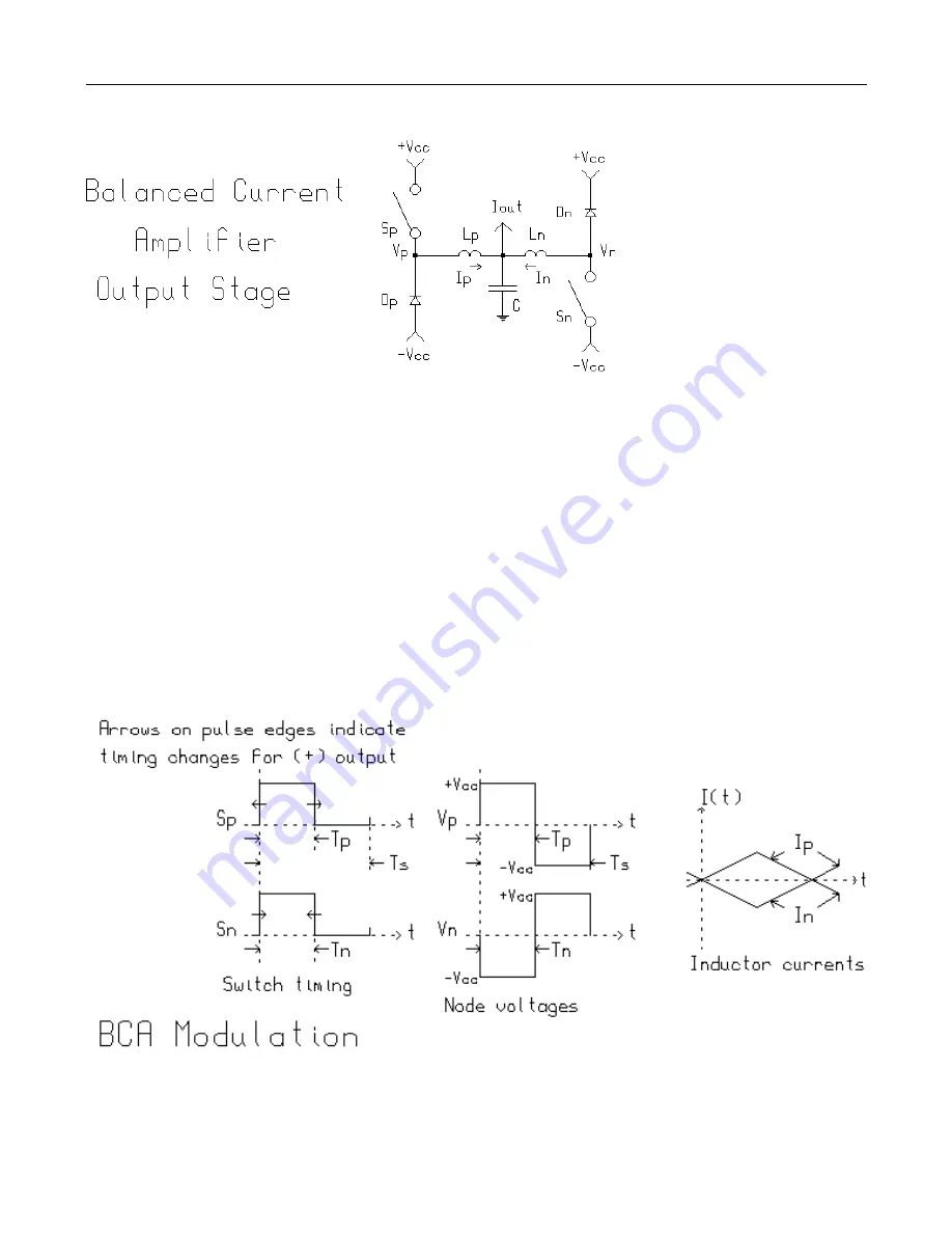
cycle). When the Sp and Sn switches are both closed
during interval Tp (or Tn) the main output inductor cur-
rent magnitudes increase at a rate of Vcc/L where
L=Lp=Ln. When the switches are both off during the in-
terval following Tp (equal to Tp=Ts-Tp), the inductor volt-
age is reversed and the output currents ramp down at
the same magnitude. Ip and In are of equal magnitude
but of opposite polarity, thus the output currents are said
to be balanced and therefore the name Balanced Cur-
rent Amplifier or BCA.
The converter is always biased
such that current continuously
flows in the output inductors which
means that either a FET (Sp or Sn)
or its companion free-wheeling di-
ode (Dp or Dn) are conducting. The
converter is said (in power conver-
sion jargon) to be operating in CCM
(continuous current mode). As
such the Vp and Vn nodes are ei-
ther at the +Vcc or -Vcc potential.
There is an equivalent circuit that
can enlighten one’s understanding
of the circuit’s operation. There are
four state permutations of the
MOSFET switches that can exist.
Two are states with one FET on, one
with no FETs on and one with both FETs on. The equiva-
lent circuit is composed of a three position switch which
can either Vcc, ground or -Vcc to an output in-
ductor of value L/2 where L=Lp=Ln. This equivalent cir-
cuit will be switched to ground whenever both Sp and
Sn switches are in the same state (on or off). If only one
of the Sp and Sn switches is on, the equivalent circuit
switch will be set to the supply polarity of the Sp or Sn
switch which is on.
4


