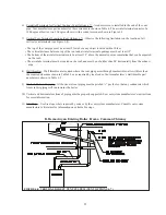

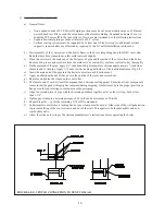


Method 1: Primary/Secondary Piping - Boiler in Secondary Loop
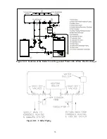
This method can be used in heat-only applications as shown in Figure 8.2 or with an indirect water heater as
shown in Figure 8.3. This method relies on primary/secondary pumping to ensure that the required flow is
always maintained through the boiler. In this system, the flow rate through the boiler is completely independent of
the flow rate through the heating system. Use the following guidelines to ensure that the boiler will have the required
flow shown in Table 8.1 regardless of the flow in the heating system.
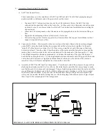
1) Primary Loop Piping - Size the primary circulator and piping to obtain the design flow rate through the heating
system as you would on any other heating system. All piping between the expansion tank and secondary
connection tees must be at least as large as that shown in Table 8.5, column (a). In order to keep the flow rates in
the primary and secondary loops independent of each other, provide at least 8 diameters of straight pipe upstream
of the first secondary tee and 4 diameters downstream of the second secondary tee. Keep the distance between the
expansion tank and the first secondary tee as short as practical.
2) Secondary Loop (“Boiler Loop”) Piping – All piping must be the size shown for the boiler in Table 8.5, column
(a). To size the circulator:
a) Select one of the boiler water flow rates shown in Table 8.5, column (b) for the boiler being installed. When
selecting the required boiler flow rate, keep in mind that if the flow rate in the primary loop exceeds the flow
rate through the boiler, it will not be possible to obtain a 180F supply temperature in the primary loop. This is
because the supply water exiting the boiler will be mixed with cooler system return water before entering the
radiation.
b) Count all fittings in the planned secondary loop (the secondary loop consists of the shaded piping in Figure
8.4a). In doing so, do not count the secondary connection tees, unions, or the fittings supplied with the boiler
(these have already been accounted for).
c) Using Table 8.7, find the equivalent lengths of all fittings in the secondary loop. Total these equivalent lengths
and add them to the total length of planned straight pipe in the secondary loop. The result is the total equivalent
length of the secondary loop.
d) Using Table 8.5, find the boiler size being installed and select a boiler secondary circulator that shows a
“maximum equivalent length” (column e) in excess of the total equivalent length calculated in Step (c).
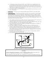
3) Indirect Water Heater Loop Piping (If Indirect Water Heater is Used) – All piping must be the size shown in Table
8.6, column (a). If the indirect water heater connections are smaller than the pipe size called for in column (a),
reduce the pipe size at the indirect water heater connections. To size the circulator:
a) Count all fittings in the planned Indirect Water Heater Loop (the indirect water heater loop consists of the
shaded piping in Figure 8.4b). In doing so, you will be counting some piping and fittings which are common to
the heating system secondary (“boiler loop”) piping and which were counted in Step 2a above. Do not count the
elbows or fittings supplied with the boiler.
b) Using Table 8.7, find the equivalent lengths of all fittings in the indirect water heater loop. Total these
equivalent lengths and add them to the total length of planned straight pipe in the indirect water heater loop.
The result is the total equivalent length of the indirect water heater loop.
c) Using Table 8.6, find the boiler size being installed and select an indirect water heater loop circulator that shows
a “maximum equivalent length” (column f) in excess of the total equivalent length calculated in Step b.
Example – Assume that a BWC150 is to be installed in a heating system along with a Crown MS-40
indirect water heater. A total of 15 ft of straight pipe will be installed between the boiler and the primary loop. A total of
20 ft of straight pipe will be installed between the boiler and the indirect water heater. Fittings are arranged as shown in
Figure 8.3. The MS-40 requires a flow rate of 8 GPM and has a head loss of 3.0 ft.
Total fittings in Secondary loop (“boiler loop”):
7 90 Elbows
2 Runs of Tees
1 Swing Check
2 Isolation Valves
Note: Unions, Secondary Connection Tees, and factory supplied fittings are ignored.
Calculate total equivalent length from Table 8.7:
15ft Straight Pipe + 7 Elbows x 3.75 + 2 Runs of Tees x 2.5 + 1 Swing Check x 10 + 2 valves x 0.8 = 57.85
Equivalent Feet Straight Pipe. From Table 8.5, we see that a Taco 007 will pump 8 GPM through a BWC150
with 148 equivalent feet of pipe, so Taco 007 is OK.
Total fittings in Indirect Water Heater Loop:
6 90 Elbows
2 Turns in Tees
1 Swing Check
2 Isolation Valves
25
Содержание BIMINI BWC225
Страница 2: ......
Страница 22: ...20 PAGE INTENTIONALLY LEFT BLANK ...
Страница 23: ...21 PAGE INTENTIONALLY LEFT BLANK ...
Страница 24: ...22 PAGE INTENTIONALLY LEFT BLANK ...
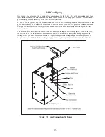
Страница 29: ...Figure 8 3 Piping Method 1 Heat Indirect Water Heater 27 ...
Страница 37: ...Figure 9 1 Wiring Connections Diagram 35 ...
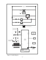
Страница 38: ...Figure 9 2 Ladder Diagram 36 ...
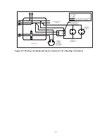
Страница 39: ...Figure 9 3 Wiring of Isolation Relay for Control of Two Heating Circulators 37 ...
Страница 56: ...54 PAGE INTENTIONALLY LEFT BLANK ...
Страница 60: ...58 ...
Страница 61: ...59 ...
Страница 62: ...60 ...
Страница 63: ...61 Gas Train Assembly Honeywell Valve ...
Страница 64: ...Gas Train Assembly Dungs Valve 62 ...
Страница 66: ...64 ...
Страница 68: ...66 ...
Страница 69: ...67 ...
Страница 70: ...68 ...
Страница 72: ......


