


9
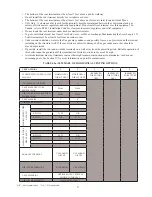
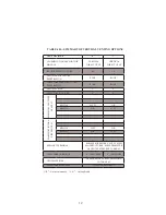
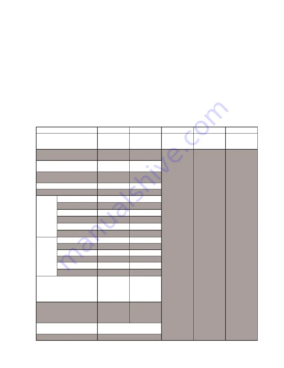
TABLE 6.2a: SUMMARY OF HORIZONTAL VENTING OPTIONS
VENT OPTION #
1
2
3
4
5
CLASSIFICATION USED IN THIS
MANUAL
HORIZONTAL
DIRECT VENT
HORIZONTAL
DIRECT VENT
(RESERVED
FOR FUTURE
USE)
(RESERVED
FOR FUTURE
USE)
(RESERVED
FOR FUTURE
USE)
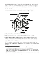
ILLUSTRATED IN FIGURE
6.1
6.1
VENT PIPE STRUCTURE
PENETRATION
WALL
WALL
AIR INTAKE PIPE STRUCTURE
PENETRATION
WALL
WALL
VENT PIPE SIZE
3”
4”
AIR INTAKE PIPE SIZE
4”
4”
MAXIMUM
VENT
PIPE
LENGTH
BWC150
55 FT
N.R.
BWC225
N.R.
55 FT
MAXIMUM INT
AKE
PIPE LENGTH
BWC150
60 FT
N.R.
BWC225
N.R.
60 FT
EXHAUST TERMINAL
3” 90 ELBOW
OR TEE
4” 90 ELBOW
OR TEE
AIR INTAKE TERMINAL
4” 90 ELBOW
4” 90 ELBOW
VENT MATERIAL
APPROVED VENT SYSTEM
SHOWN IN TABLE 6.5
AIR INTAKE MATERIAL
GALVANIZED OR PVC
“N.R” - Not recommended “N.A.” - Not applicable
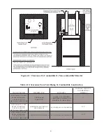
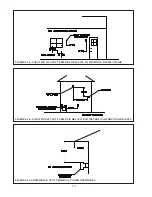
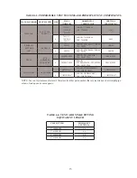
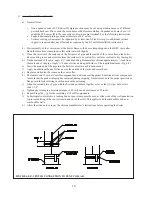
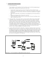
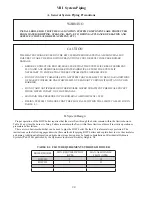
• The bottom of the vent terminal must be at least 7 feet above a public walkway.
• Do not install the vent terminal directly over windows or doors.
• The bottom of the vent terminal must be at least 3 feet above any forced air inlet located within 10 feet.
• USA Only: A clearance of at least 4 feet horizontally must be maintained between the vent terminal and gas
meters, electric meters, regulators, and relief equipment. Do not install vent terminal over this equipment. In
Canada, refer to B149.1 Installation Code for clearance to meters, regulators and relief equipment.
• Do not locate the vent terminal under decks or similar structures.
• Top of vent terminal must be at least 5 feet below eves, soffits, or overhangs. Maximum depth of overhang is 3 ft.
• Vent terminal must be at least 6 feet from an inside corner.
• Under certain conditions, water in the flue gas may condense, and possibly freeze, on objects around the terminal
including on the structure itself. If these objects are subject to damage by flue gas condensate, they should be
moved or protected.
• If possible, install the vent and air intake terminals on a wall away from the prevailing wind. Reliable operation of
this boiler cannot be guaranteed if the terminal is subjected to winds in excess of 40 mph.
• Air intake terminal must not terminate in areas that might contain combustion air contaminates, such as near
swimming pools. See Section IV for more information on possible contaminates.
Содержание BIMINI BWC225
Страница 2: ......
Страница 22: ...20 PAGE INTENTIONALLY LEFT BLANK ...
Страница 23: ...21 PAGE INTENTIONALLY LEFT BLANK ...
Страница 24: ...22 PAGE INTENTIONALLY LEFT BLANK ...
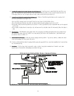
Страница 29: ...Figure 8 3 Piping Method 1 Heat Indirect Water Heater 27 ...
Страница 37: ...Figure 9 1 Wiring Connections Diagram 35 ...
Страница 38: ...Figure 9 2 Ladder Diagram 36 ...
Страница 39: ...Figure 9 3 Wiring of Isolation Relay for Control of Two Heating Circulators 37 ...
Страница 56: ...54 PAGE INTENTIONALLY LEFT BLANK ...
Страница 60: ...58 ...
Страница 61: ...59 ...
Страница 62: ...60 ...
Страница 63: ...61 Gas Train Assembly Honeywell Valve ...
Страница 64: ...Gas Train Assembly Dungs Valve 62 ...
Страница 66: ...64 ...
Страница 68: ...66 ...
Страница 69: ...67 ...
Страница 70: ...68 ...
Страница 72: ......


