
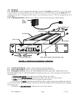


S1 - AGC/MGC Select
- Slide switch selects
Manual (MGC) or Automatic (AGC) gain control. In
MGC use R40 to adjust the gain.
FIGURE 2.2 2097 Front Panel Controls and Indicators
R40 - Manual
Gain Control
-
Multi-turn
potentiometer
adjusts the gain in
the manual gain
(MGC) mode.
Clock-wise
increases gain
TP3, TP4 Gain Control Voltage
- DC
Voltage from 0 to -2 volts, 1K impedance,
increases as the gain increases in AGC only
DS2 - DC Power LED
-
Lights green when DC
power is present
2097 AMPLIFIER
C
ROSS
T
ECHNOLOGIES, INC.
DC
GND AGC
MGC
AGC MGC
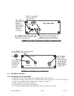
FIGURE 2.3 2097 Inputs and Outputs
J2 - IF Output
-
The IF 70 MHz
output . This is a
50
Ω
, BNC output at
-35 dBm level. The
gain is automatically
adjusted in AGC to
-35 dBm output and
by R40 in MGC.
J3 - DC POWER
- The +15 VDC unregulated
DC voltage from the wall power supply
J1 - 70 MHz IN
- The 70 MHz IF
input. This is at a 0
to -80 dBm level.
This is a 50
Ω
,
BNC, female
connector.
GND +15
C
ROSS
T
ECHNOLOGIES, INC.
70 MHZ IN
DC
70 MHZ
OUT
2 . 5
Installation / Operation -
2 . 5 . 1 Installing and Operating the 2097 -
1.) Check that S1 is set to the desired position. Normal operation is AGC (Figure 2.2)
2.) If using the wall power supply, connect it to the 2097 and the wall power supply to 115 VAC, 60 Hz (Figure 2.1)
3.) Connect a 0 to -80 dBm signal to 70 MHz IF In, J1 (Figure 2.1, Figure 2.3)
4.) Connect the IF OUT, J2, to the external device
5.) Be sure DS2 (green, DC Power) is on (Figure 2.2).
6.) To check proper operation and adequate signal level, monitor TP3, TP4 with a voltmeter.
2097 manual Rev 0
Page 5
3/13/03


