


2 . 0
Installation
2 . 1
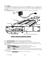
Mechanical - The 2097 is packaged in an aluminum extrusion. The -R option is mounted on a 1 3/4” X 19” panel that
can be mounted to a rack using the 4 holes at the ends. Both units DC from the wall power supply (option -P) (+15V
unregulated). See Figure 2.1. Optionally, the 2097, option -C is powered from an ex15 VDC power supply like the Cross
model 2000-01.
2 . 1 . 1 Cleaning Instructions - Wipe the exterior with a dry, soft cloth. Use no detergent or cleaning chemicals.
2 . 2
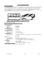
Controls and Indicators - Figure 2.2 shows front panel controls and indicators.
2 .3 Input / Output Signals - Figure 2.3 shows the input and output signals to the 2097.
2 . 4
Accessing the PC Card - There are NO USER JUMPERS or other on-card controls. ALTHOUGH IT IS NOT
RECOMMENDED AND MAY VOID THE WARRANTY the following shows how to remove the printed circuit board (PCB)
from the extrusion:
1.) Always remove power when installing or removing the PCB from the extrusion
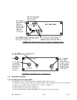
2.) Remove four (4) rear panel screws (see Figure 2.1). Remove any other screws on the extrusion.
3.) Gently pull the rear panel and PCB assembly completely out of the extrusion.
4.) To install the PCB gently push the rear panel and PCB assembly completely into the extrusion Make sure the shield
goes in the lower channel and the PCB in the next channel above that in the extrusion and that the front panel controls go through
the front panel holes.
5.) Install four (4) rear panel screws. Install any other screws on the extrusion.
2097 manual Rev 0
Page 4
3/13/03
IF LVL REM GAIN ALARM FREQUENCY (GHZ) TUNE
8
1. 3
3
2004 TEST UPCONVERTER
CROSS TECHNOLOGIES, INC.
-25 -45 -65
UP DOWN
FIGURE 2.1 SERIES 2000 ASSEMBLY DRAWING
EXTRUSION
BACKPLANE
REAR SCREWS (4EA)
FRONT SCREWS (4EA)
FRONT PANEL
RACK MOUNT PANEL (FOR -R MODELS ONLY)
PCB ASSEMBLY
WALL
POWER
S U P P L Y


