Cross Technologies 2083-0703 Скачать руководство пользователя страница 10

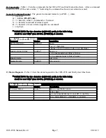
2.2  Rear Panel Input/Output Signals
Figure 2.1 shows the input and output connectors on the rear panel.

AC

GND

J20

J2

J1

J10

MONITOR

AND

CONTROL

1

5 2

3

4

6

7

8

9

AC1 - POWER IN
AC input for switching 
power supply.  
100-240 ±10% VAC, 
47-63 Hz.

J10 - MONITOR AND CONTROL
DB9 female connector.  
See Table 2.1

J20 - ETHERNET CONNECTOR
RJ45 Ethernet Connector
(Optional)

RF IN

IF OUT

J2 - IF (RF OUT) 
OUTPUT
50

Ω

 BNC connector 

370 ±75 MHz,
-30 to -5 dBm output

J1 - RF INPUT
50

Ω

 Type-N connector 

720 ±75 MHz,
-50 to -25 dBm input
See Table 2.2.

J18

J3

J18 - EXT REF 
OUTPUT
+3 ±3 dB 
10 MHz 
Ext. Ref. Output

10 MHz REF

OUTPUT

10 MHz REF

INPUT

J3 - EXT REF INPUT
+3 ±3 dB 
10 MHz Ext. Ref. Input**

FIGURE 2.1     2083-0703 Rear Panel I/O

ʼ

s

TABLE  2.1  JJ10 

TABLE  2.1  J10  Pinouts*

Pin

Function

1

Rx-

2

RS232C

3

RS232C

4

Tx-

5

GND

6

Alarm Relay: Common

7

Alarm Relay: Normally Open

8

Not Used

9

Alarm Relay: Normally Closed

TABLE  2.2  IInput/Output 

2.2 I

nput/Output  Connectoor 

Connect

or  Options

Option

Input

Output

STD

50

Ω

, N

50

Ω

, BNC

D

50

Ω

, BNC

50

Ω

, BNC

SS

50

Ω

, SMA

50

Ω

, SMA

*Remote Serial Interface

Interface: DB-9 Male
Protocol: RS232C (RS232C/422/485 Option Q), 
9600 baud rate, no parity, 8 data bits, 1 start bit, 1 stop bit.

**External Reference Input

Unit detects presence of EXT Input and automatically switches to EXT Reference.
User is responsible for the suitability of applied input (Frequency Accuracy, Phase Noise, etc.)

2083-0703 Manual, Rev. 0


                Page 10


       08/24/15

Содержание 2083-0703

Страница 1: ...reproduced or duplicated without the prior permission of Cross Technologies Inc for purposes of operating the equipment Printed in USA When ordering parts from Cross Technologies Inc be sure to includ...

Страница 2: ...r Cross Technologies Inc s obligation under this warranty is limited to repairing or at Cross Technologies Inc s option replacing parts subassemblies or entire assemblies Cross Technologies Inc shall...

Страница 3: ...and output The external 10 MHz Option E includes a 10 MHz output connector which contains either the internal or external 10 MHz reference signal It is powered by a 100 240 10 VAC power supply and in...

Страница 4: ...B at Fc 1 1 dB steps manually adjustable Gain Range 370 75 MHz Frequency 50 12 dB Impedance Return Loss 15 dBm minimum No Damage Input Level 50 to 25 dBm Input Level 720 75 MHz Frequency 50 12 dB Impe...

Страница 5: ...without notice Cross Technologies Inc 2015 Contact Cross Technologies Inc for other options Ethernet with Web Browser SNMP W18 Communication Interface Standard RS232 Ethernet with Web Browser W8 Ether...

Страница 6: ...8 9 Female DB 9 PC Com Port Male DB 9 2015 16 17 M C Port M C Cable Diagram Cross Technologies Frequency Converters RX RX TX TX DTR SG DSR RTS CTS SG Connector Rear panel DB 9 female Pinouts RS 485 42...

Страница 7: ...Comma ands Commands Command Syntax Description Set Transmit Gain aaC3xx where xx 2 characters Range 0 to 20 0 dB to 20 dB in 1 1 dB steps Enable External 10MHz aaCEx where x 0 to disable External 10M...

Страница 8: ...e operation of the equipment is not compromised Additional space between units may be required E Circuit Overloading Consideration should be given to the connection of the equipment to the supply circ...

Страница 9: ...h high by 16 inch deep chassis A switching 12 24 5 VDC power supply provides power for the assemblies The 2083 0703 can be secured to a rack using the 4 holes on the front panel Figure 2 0 shows how t...

Страница 10: ...EF INPUT J3 EXT REF INPUT 3 3 dB 10 MHz Ext Ref Input FIGURE 2 1 2083 0703 Rear Panel I O s TABLE 2 1 J J10 TABLE 2 1 J10 Pinouts Pin Function 1 Rx 2 RS232C 3 RS232C 4 Tx 5 GND 6 Alarm Relay Common 7...

Страница 11: ...s not function in the normal display mode MENU EXECUTE 720 370 G 20 REF INT POWER ALARM S3 MENU EXECUTE BUTTON Press to get into Program mode and to execute any changes DS6 ALARM LED Red LED indicates...

Страница 12: ...is off Figure 2 2 5 AC Fuse The fuse is a 5 mm X 20 mm 2 amp slow blow Type T and is inserted in the far slot in the drawer below the AC input as shown in Figure 2 3 There is a spare fuse in the near...

Страница 13: ...R is selected in any of the above menus or when operator reaches the end Alarm indications appear on the LEDs see figure 2 2 All program changes must start with the operation of the Menu Execute switc...

Страница 14: ...the operator may desire 2 5 3 Control Switches 1 Menu Execute Any change to the programming of the unit must be initiated by pressing the Menu Execute switch and completed by pressing the Menu Execute...

Страница 15: ...t or right Pressing the Up Down switch down will toggle the display digit selected until you have the desired gain NOTE THE GAIN WILL BE CHANGED AS YOU ADJUST THE NUMBERS HOWEVER THE VALUE WILL NOT BE...

Страница 16: ...SPLAY PUSHING MENU EXECUTE SEQUENCE REV 1 00 720 370 G 20 REF INT REMOTE OFF EXT REF OFF SCROLL SCROLL PUSH BUTTON PUSH BUTTON Power Up Normal Display Menu 1 Gain 0 to 20 Menu 2 Set Unit to Remote Ope...

Страница 17: ...INC 6170 Shiloh Road Alpharetta Georgia 30005 770 886 8005 FAX 770 886 7964 Toll Free 888 900 5588 WEB www crosstechnologies com E MAIL info crosstechnologies com Printed in USA 2083 0703 Manual Rev...

Отзывы: