background image

- 4 -

1. INTRODUCTION

Two different types of Remote Interface permit full remote control of the
microhmmeter by an external computer using either the RS-232 serial interface or the
IEEE-488 parallel interface. The measured value and instrument status can also be
read by the computer.

The software commands are common to both interfaces and generally follow the
IEEE488.2/SCPI format. Either or both interfaces can be fitted to the instrument,
however, only one of these can be in use at any one time.

An additional interface can be fitted which permits more basic control of the
microhmmeter by a Programmable Logic Controller (PLC) or similar device. The
Analogue Output feature is also included on the PLC card.

Selection of the optional interfaces, together with additional features such as Baud
Rate and addresses, are set from the front panel menu.

All interface connectors are accessible on the rear panel.

The RS-232 interface requires Ver 2.0 software, or higher.

The IEEE-488 interface requires Ver 3.0 software, or higher.

The PLC interface requires Ver 4.0 software, or higher.

2. RS-232 SERIAL INTERFACE

2.1 Connection

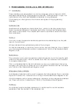
This conforms to specific ation ANSI/EIA/TIA-232-E-1991 "Interface Between Terminal
Equipment and Data Circuit-Terminating Equipment Employing Serial Binary Data
Interchange." A list of pin assignments is given in Appendix II.

Signal levels;

MARK  (logical "1");

-3V to -15V

SPACE (logical "0");

+3V to +15V

Data is transferred using the TXD and RXD lines.

Hardware handshaking for each character transfer uses the RTS and CTS lines.

RTS is an output from the microhmmeter which indicates its receiver status. When
asserted (low) it indicates that it is ready to receive another character. When negated
(high) the microhmmeter receiver buffer is full and cannot receive another character
until the buffer is processed (if the PC sends one it may be lost). As soon as space
becomes available in the receiver buffer,  RTS is re-asserted to allow the PC to send
the next character.

When the microhmmeter detects receipt of a line terminator character, RTS is
negated whilst the command line buffer is read and validated. This is to prevent the
PC sending further characters whilst  a command is being validated.  Following
validation, RTS is re-asserted to permit the next command to be transmitted by the
PC.

CTS is an input to the microhmmeter and controls the transmission of characters. If
the PC asserts CTS (low) then the microhmmeter will transmit the next character from
the output buffer (if one is waiting). If the PC negates CTS (high) then the
microhmmeter will not transmit  the characte r, but will wait until CTS is re-asserted.
TXD will remain in the mark (low) condition whilst CTS is negated. Note that changing
CTS during transmission of a character will not disrupt the transmission of that
character.

Содержание DO5000 Series

Страница 1: ...INTERFACES FOR DO5000 SERIES DIGITAL MICROHMMETERS USER MANUAL Issue 7 0 1st October 2002 Cropico Pt No 610017 Ver 7 0 Test Equipment Depot 800 517 8431 99 Washington Street Melrose MA 02176 TestEqui...

Страница 2: ...2000 Reflects new treatment of Temperature Compensated resistance in Version 5 0 software Also includes minor variations for the DO5001 and DO5002 models Issue 6 0 ECN 136 05 02 2001 Includes minor v...

Страница 3: ...RS 232 Interface Commands 14 4 3 Configuration Measurement Commands 14 4 4 Data Operation Commands 17 4 5 Other function Commands 19 4 6 System Related Commands 21 4 7 Status Reporting Commands 22 4...

Страница 4: ...t of pin assignments is given in Appendix II Signal levels MARK logical 1 3V to 15V SPACE logical 0 3V to 15V Data is transferred using the TXD and RXD lines Hardware handshaking for each character tr...

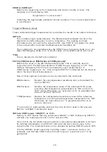
Страница 5: ...er without the need for a PC Select ON to set the Talk Only mode In this mode the interface will ignore all incoming interface commands and the instrument will remain in LOCAL control mode The result...

Страница 6: ...as the main display If the Temperature Compensation is selected then the compensated resistance will be sent See section 4 1 for output data format Addressable Mode On selecting Address Addr the curre...

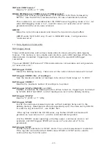
Страница 7: ...selective device clear DT1 Device Trigger Function The device may be triggered by the appropriate commands C0 Controller Function The controller function is not implemented and hence the instrument c...

Страница 8: ...t This is used by one or more devices to indicate the need for attention and can act as an interruption of the current sequence of events Typically SRQ indicates data is ready to transmit and or an er...

Страница 9: ...a pre defined device dependent state Recognising devices respond whether they are addressed or not The effect of DCL is as follows The parser is reset to await a new command The output queue is flushe...

Страница 10: ...dent Messages This is known as Data Mode These messages are described fully in Section 4 3 7 Serial Poll A Serial Poll is a sequence which enables the controller to learn if a device or group of devic...

Страница 11: ...ust not be sent as the first character This is treated as a non recognised character and the command error bit 5 of the Standard Event Register is set Semicolon The semicolon is also used to separate...

Страница 12: ...is produced e g SENSe FRESistance RANGe 30OHM 300OHM ignored In the description of commands that follows various symbols are used for different features parameter represents a field name ON OFF the v...

Страница 13: ...h engineering exponents reflecting the resolution and units displayed on the LCD screen e g Display Returned Value 30 321 30 321 30 range 29 657 K 29 657E 3 30K range 106 45 m 106 45E 3 200m range If...

Страница 14: ...232 operation All keys on the front panel are fully functional This is the default at power up SYSTem REMote Places the instrument in the remote mode for RS 232 operation All keys on the front panel a...

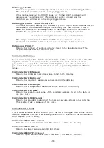
Страница 15: ...FAST Sets the measurement mode Slow mode produces approximately two readings per second gives the best noise immunity and all features are available Medium mode gives a 1 5x to 2x improvement in spee...

Страница 16: ...ering is on then repeated FETCh commands can be made to return the most recent measurement One of three optional functions can be included with this command FRESistance Returns the uncompensated resis...

Страница 17: ...LEAr Clears the datalog memory Take care all the current stored values will be lost DATAlogger COUNt No of readings Sets the maximum number of readings to be stored Valid range is 1 to 4000 DATAlogger...

Страница 18: ...current contents of the data log A minimum of 2 readings must be stored otherwise an execution error is generated i e bit 4 of the Standard Event Register is set This error is also generated if the l...

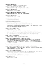
Страница 19: ...manually entered temperature the unit of which is the current temperature unit C or F Range is 0 100 C 32 212 F SENSe TCOMpensate MODE Returns EXT or MAN manual temperature SENSe TCOMpensate REFerenc...

Страница 20: ...r for the measurement to be defined as settled SENSe SETTling LIMit Returns the maximum number of display digits selected Selecting the Settling facility will Deselect the Filter facility Change Avera...

Страница 21: ...ime Use 24 hour clock format SYSTem TIME Queries the system clock time Returns hh mm ss in 24 hour clock format SYSTem DATE yyyy mm dd Set the system calendar date SYSTem DATE Queries the system calen...

Страница 22: ...ad at any time using the appropriate query command The Event Register detects 0 to 1 transitions in the Condition Register and the appropriate bit is set The register value can be read at any time usi...

Страница 23: ...sistance 0 Below Lower Limit Above Upper Limit 0 0 0 15 14 13 12 11 10 9 8 7 6 5 4 3 2 1 0 0 0 0 0 Measuring 0 0 0 Measurement 0 0 0 0 0 0 0 15 14 13 12 11 10 9 8 7 6 5 4 3 2 1 0 Operation Complete 0...

Страница 24: ...STATus QUEStionable EVENt Query the Questionable Data Event Register The instrument returns a binary weighted decimal value representing the bits set in the event register and clears it STATus QUEStio...

Страница 25: ...uring bit 4 This bit is set when a new measurement starts and is cleared when complete Measurement Available bit 8 This bit is set when a new measurement started by the INITiate command has completed...

Страница 26: ...synchronising data transfers from the instrument The application programme can poll the bit to detect when a measurement is complete and data is available Alternatively for IEEE the corresponding enab...

Страница 27: ...ction with non query commands and is only available for IEEE If the OPC is sent in RS 232 mode it will generate a command error and the command is ignored Example Data logging can take an appreciable...

Страница 28: ...an continuously poll the Message Available bit using STB The Status Byte Register can also be read by an IEEE 488 1 serial poll sequence 4 8 Front Panel Operations The currently selected interface is...

Страница 29: ...c Controller or similar device The facilities it provides are Triggering of measurements Selection from 10 stored set up memories which are user programmable via the front panel See main Operation Man...

Страница 30: ...0 mS Fast mode 240 mS 5 5 Description of Input Output signals Inputs COM IN Common line for all inputs CTRLIN Requests remote control of the microhmmeter and locks the keyboard When released control w...

Страница 31: ...Remote Interface See Front Panel Set up When CTRLIN is asserted the Keyboard is locked If no Remote Interface is selected when CTRLIN is asserted then the PLC will be selected automatically If the RS...

Страница 32: ...asurement 5 7 Analogue Output This is selected from the Remote Interface PLC menu see Front Panel Set up When fitted and selected ON it produces an output voltage proportional to the measured resistan...

Страница 33: ...Memory 5 Test failed resistance too high Figure 2 Subsequent measurement using Memory 3 Test passed CTRLIN N0 MEASURE N1 N2 N3 CTRLOUT PASS FAIL HIGH FAIL LOW ERROR EOT CTRLIN N0 MEASURE N1 N2 N3 CTR...

Страница 34: ...igure 3 Connecting the unit with the internal supply 25V CTRLIN 4 N0 17 N1 5 N2 18 N3 6 MEASURE 7 25V 3 0V 2 COM IN 16 COM OUT 8 CTRLOUT 21 EOT 22 PASS 10 FAIL HIGH 9 FAIL LOW 20 ERROR 23 DO5000 PLC S...

Страница 35: ...ure 4 Connecting the unit with an external supply 25V CTRLIN 4 N0 17 N1 5 N2 18 N3 6 MEASURE 7 25V 3 0V 2 COM IN 16 COM OUT 8 CTRLOUT 21 EOT 22 PASS 10 FAIL HIGH 9 FAIL LOW 20 ERROR 23 25V PLC SYSTEM...

Страница 36: ...ddress UNL Unlisten MTA My Talk Address UNT Untalk Programming Language Both interfaces use the same commands For the RS 232 interface these commands are sent as part of a serial string For the IEEE 4...

Страница 37: ...it STATe ON OFF or 1 0 LIMit STATe LIMit ALARm ON OFF or 1 0 LIMit ALARm Temperature Compensation Commands SENSe TCOMpensate STATe ON OFF or 1 0 TCOMpensate STATe TCOMpensate MODE EXT or MAN manual te...

Страница 38: ...em Related Commands DISPlay BRIGhtness ON OFF or 1 0 DISPlay BRIGhtness SYSTem BEEPer BEEPer STATe ON OFF or 1 0 BEEPer STATe VERSion TIME hh mm ss TIME DATE yyyy mm dd DATE IDN RST TST WAI Status Rep...

Страница 39: ...39 RS 232 Interface Commands SYSTem LOCal REMote Test Equipment Depot 800 517 8431 99 Washington Street Melrose MA 02176 TestEquipmentDepot com...

Страница 40: ...EE 488 Pin Connections 1 DIO1 Data Input Output 1 2 DIO2 Data Input Output 2 3 DIO3 Data Input Output 3 4 DIO4 Data Input Output 4 5 EOI End Or Identify 6 DAV Data Valid 7 NRFD Not Ready For Data 8 ND...

Страница 41: ...5VDC 4 CTRLIN 5 N1 6 N3 7 MEASURE 8 COM OUT 9 FAIL HIGH 10 PASS 11 ANALOGUE OUTPUT LOW 12 CASE 13 No Connection 14 No Connection 15 No Connection 16 COM IN 17 N0 18 N2 19 Spare Input 20 FAIL LOW 21 CT...

Отзывы: