background image

WIRING INSTRUCTIONS 


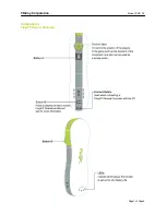
PROGRAM/OVERRIDE SWITCH: 2 PIN PLUG 

This switch is used for programming features, transmitters, valet mode, and to override the optional starter disable (if 
installed) in the event of a non-operating remote control. 


LED: 2 PIN PLUG 

The LED is used as a VALET/PROGRAMMING indicator and it will also FLASH for use as security deterrent when the 
optional ANTI-GRIND/STARTER DISABLE output is programmed. 


12 PIN PLUG: 

PIN 1: WHITE: +12V or (-) NEGATIVE PARKING LIGHT OUTPUT: 

Connect to vehicle parking light circuit at the back of light switch or if this is not possible, connect directly to one of the 
parking lights at the front of the vehicle.  If your vehicle has a multiplex lighting system that requires a (-) Negative parking 
light output, then open the access door on the top of the module and move the jumper.  SEE JUMPER PLUG DIAGRAM 
PAGE 8.  Some European vehicles require separate left and right circuits.  Use a dual relay or diodes to isolate the output. 

NOTES: (1) Default parking light output is +12 volts. (2) Use an external relay for vehicles that draw excess 
current from extra running lights, light bars, or trailers.  Parking light output is limited to +15/-.5 AMPS only.


PIN 2: YELLOW/WHITE: (-) HORN CHIRP/HONK OUTPUT 

Connect to the Negative Horn Trigger wire usually located near the steering column.  If the vehicle horn circuit requires 
+12V, then a relay is required.  RELAY WIRING: Connect the Yellow/White wire to terminal 85, connect relay terminals 86 
and 87 to +12V constant power. Connect terminal 30 of the relay to the +12V positive Horn activation wire.


PIN 3: BLACK: MAIN SYSTEM GROUND 

Connect to chassis metal of the vehicle.  An existing bolt or screw may provide an adequate ground, or drill a small hole, 
scrape away paint and attach using a sheet metal screw & star washer.  This wire must be connected to a proper ground 
or undesirable and inconsistent operation will occur.  Do not use Factory ground locations. 


PIN 4: YELLOW/BLACK: (-) IGNITION OUTPUT -or- ANTI-GRIND/STARTER DISABLE OUTPUT 

This negative output wire is programmable and can function two different ways. It can be used as a Negative Ignition 
output for GM Anti-theft and Transponder Bypass modules, or it can be programmed to function as an Anti grind/Starter 
Disable output.  As a Negative Ignition wire, this wire activated when the remote start button is pressed and stays on 
through the duration of the remote start.  As an Anti grind/Starter disable this wire activates when the Lock button on the 
remote is pressed and during remote start.  When using this wire for an Anti grind/Starter disable, an optional Relay is 
needed to interrupt the Starter circuit.  The starter disable circuit adds an anti-theft feature to this remote start system and 
to prevent accidental grinding of the starter if key is turned to far after a remote start.  See diagrams on NEXT PAGE. 


Содержание CoolStart RS-900

Страница 1: ...ubject to repair or replacement charges USE A VOLT OHM METER to test and locate all connections Test Lights can damage a vehicle s computer systems ADDITIONAL PARTS which are not included with this un...

Страница 2: ...self propelled threat to life and property DO NOT extend the RS900 901 999FM Remote start ignition harness length Mount the module so that main harness reaches all ignition switch wiring Extending th...

Страница 3: ...le horn circuit requires 12V then a relay is required RELAY WIRING Connect the Yellow White wire to terminal 85 connect relay terminals 86 and 87 to 12V constant power Connect terminal 30 of the relay...

Страница 4: ...N If needed IGN SW OR ANTI THEFT MODULE 12V CONSTANT OR TRANSPONDER PIN 4 YELLOW BLACK FOR ANTI GRIND STARTER DISABLE OUTPUT Relay not included TO IGN 2 MOTOR ACC START CUT BROWN YELLOW BLACK 86 85 MA...

Страница 5: ...icles the RS900 901 999FM systems will wait until light turns off before attempting a remote start Note A relay may be required for vehicles that have a Positive wait to start lamp circuit Relay not i...

Страница 6: ...WHITE 30A FUSE RED 30A BROWN PINK FUEL ENGINE BATTERY PUMP ECU GRAY STARTER COIL IGN OR TRANSMISSION ACC ECU H V AC Diagram not to scale for illustration purposes only Your vehicle may differ IGN 2 A...

Страница 7: ...ndai Electric Vacuum Many mid 1980 s through mid 1990 s European makes NEGATIVE TRIGGER DOORLOCK WIRING POSITIVE TRIGGER DOORLOCK WIRING GREEN GREEN FUSED RED 12V RED BLUE BLUE 86 85 86 85 87 87 30 87...

Страница 8: ...PIN DIAGRAM Jumper pins are used to change configure the settings of the on board IGN2 ACC2 PINK WHITE and the Parking Light WHITE output relays Snap open the door on the top of the control module to...

Страница 9: ...utton 5 times after a few seconds the unit will flash the lights 5 times 4 Carefully press the program button 10 times you must get a light flash after each press 5 Press the Lock Button on the remote...

Страница 10: ...ne and close hood to abort un ground Gray wire 6 See Tach Reference programming TACH PROGRAMMING 1 Open hood or ground Gray hood pin wire if no hood pin is installed 2 Red White wire should be connect...

Страница 11: ...times then after a few seconds the unit will flash the parking lights 4 times 4 Press button 1 of the transmitter to be learned You should get 2 light flashes indication the unit is waiting for a 2nd...

Страница 12: ...low START VEHICLE 1 REMOTE VEHICLE UNLOCK LOCK START TRUNK POP 1 2 VEHICLE OPERATION VEHICLE 2 START ONLY OPTION PROGRAMMING This system has several installer programmable features as listed in the ch...

Страница 13: ...Horn Chirps on remote start ON or OFF ON OFF 8 Lock During and After Remote Start Abort ON or OFF OFF ON 9 Smart Tachless Reference Voltage Setting 9 ON or OFF OFF ON 10 Smart Tachless Reference Volta...

Страница 14: ...auxiliary output change the option to 3 Pulse and tap the green wire into a Negative signal wire on the vehicle such as a Negative door lock wire Pressing the Factory remote lock button 3 times will p...

Страница 15: ...ehicles there may be a Factory anti theft system that will not allow the engine to run without the key in the ignition These systems may include Factory Security Modules GM Passkey Passlock and RF Tra...

Страница 16: ...PURPLE TAN ORANGE YELLOW BLACK GLOW PLUG INPUT PINK NOTE USE EXTERNAL RELAYS FOR HIGH CURRENT YELLOW WHITE OEM REARM START ACTIVATION GREEN HORN CHIRP HONK OEM DISARM GREATER THAN 30A IGNITION CIRCUIT...

Отзывы: