background image

Crestron 

MPS-300


Multimedia Presentation System 300


QuickMedia Wiring


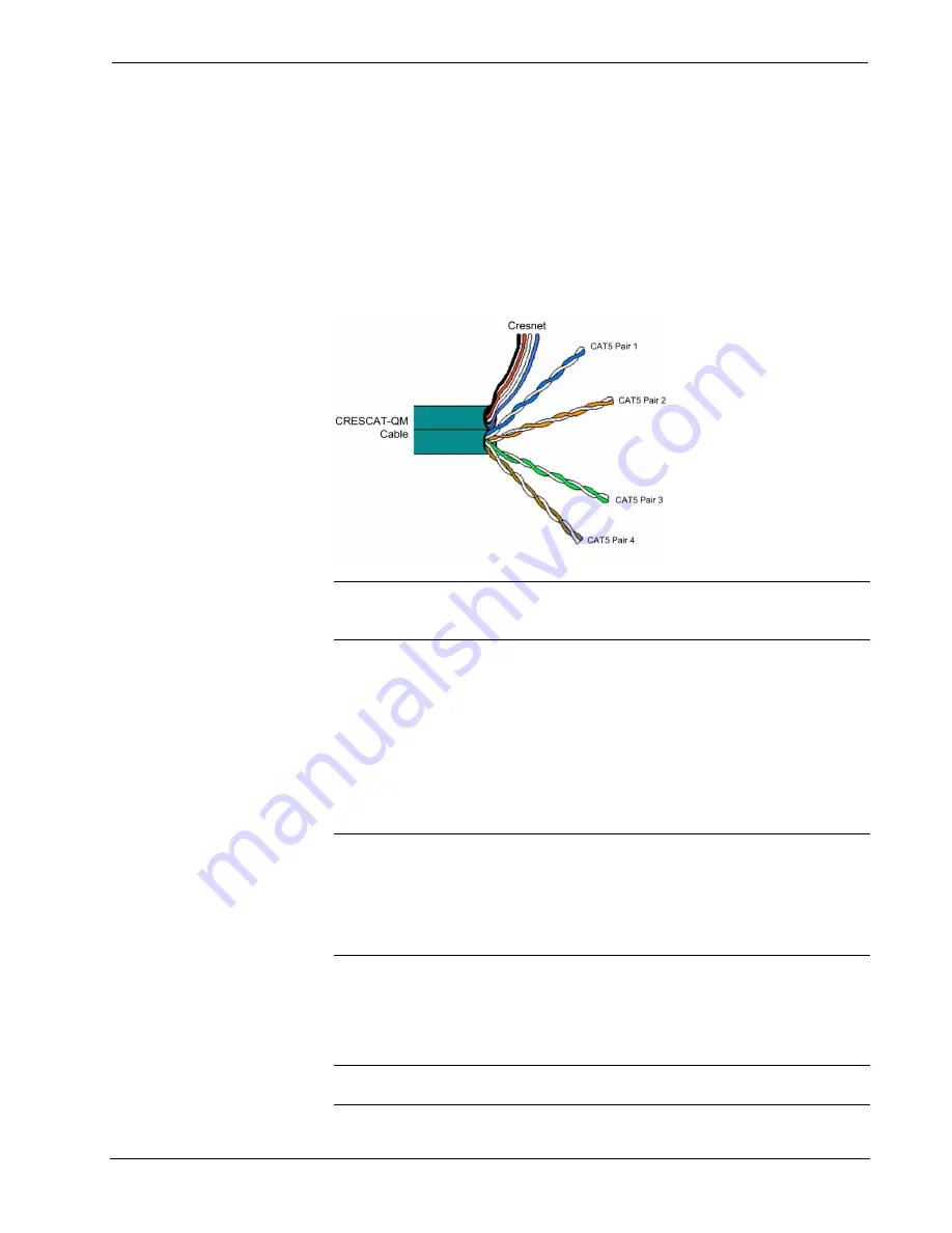
The Crestron QuickMedia cable (sold under the name “CresCAT-QM”) contains one 
CAT5E cable and one Cresnet cable in Siamese jackets. Installation of any QM 
device is as simple as installing CresCAT-QM wires from the output of one device to 
the input of another. Installations are flexible, affordable and fast. For more 
information, refer to the latest revision of the Crestron MediaManager Applications 
Guide (Doc. 6244).  

CresCAT-QM Cable 


NOTE:

  Do not untwist the two wires in a single pair for more than 1/3-1/2”  

(0.84-1.27 cm) when making a connection. The twists are critical to canceling out 
interference between the wires. 

The aggregate cable length of a signal path originating at the MPS-300 and 
terminating at a QM receiver must not exceed 450 feet (137 meters). Video signals 
may experience a loss of quality over very long lengths of cable. This phenomenon is 
due to the added resistance and capacitance of longer cable lengths and is not 
peculiar to either Crestron and/or QuickMedia systems. To ensure sufficient 
bandwidth, the maximum aggregate cable length should not exceed 450 feet. The use 
of lower-resolution signals may allow increased cable length but must be tested by 
the installer with the sources to be used. The QM pin assignment is based on the 
EIA/TIA 568B RJ-45 Jack standard. 

NOTE:

  When transmitting S-video, luminance uses the green video pathway and 

chrominance uses the red video pathway. When transmitting composite video, the 
signal is carried on the blue video pathway. 

NOTE:

  When using CresCAT-QM wiring, four additional wires are included for 

making Cresnet connections. 

When connecting multiple QM devices, the route between a QM origination point 
(transmitter) and a QM endpoint (receiver) cannot have more than two midpoints 
(e.g. QM-MD7x2 or other QM switchers). Refer to the following diagram when 
configuring a QM network. 

NOTE:

  Use CresCAT-QM to make QM connections. The cumulative skew over the 

entire length must be less than 22 ns. 

Operations Guide – DOC. 6529B 

Multimedia Presentation System 300: MPS-300  

  23 

Содержание MPS-300

Страница 1: ...Crestron MPS 300 MultimediaPresentationSystem300 Operations Guide ...

Страница 2: ...or objects have fallen into the apparatus the apparatus has been exposed to rain or moisture does not operate normally or has been dropped Disconnect power prior to connecting or disconnecting equipment Do not install in direct sunlight The apparatus must be installed in a way that the power cord can be removed either from the wall outlet or from the device itself in order to disconnect the mains ...

Страница 3: ...B Input Ports 28 Programming Software 31 Earliest Version Software Requirements for the PC 31 Programming with Crestron SystemBuilder 31 Programming with SIMPL Windows 31 Switching Programs 32 Saving Settings 32 Uploading and Upgrading 34 Establishing Communication 34 Programs and Firmware 35 Configuration Operation 36 Configuration 36 Operation 76 Problem Solving 84 Troubleshooting 84 Check Netwo...

Страница 4: ......

Страница 5: ...er stereo 20 Watt x2 70V or 100V models 2 Series control engine e Control 2 Web server 10 100 Ethernet RoomView and SNMP support Two RS 232 four IR four digital in four relay control ports Front panel setup and control Backlit LCD display Keypad touchpanel and wireless control options Internal power supply 2 space rack mountable The MPS 300 is a complete presentation control and signal routing sol...

Страница 6: ...o 450 feet over a single inexpensive CAT5e type cable Just one CresCAT QM cable and a QM receiver are all that is required for complete signal routing and device control eliminating all the bulky expensive cabling that would otherwise be needed A full range of QM transmitters receivers and other products is offered by Crestron to suit any application For QuickMedia wiring use CresCAT QM P CresCAT ...

Страница 7: ...ble offering the choice of 8 ohm stereo 70V mono or 100V mono outputs For large rooms requiring more power the MPS 300 supports plug and play compatibility with Crestron s QM Series 3 channel amplifiers providing a complete solution for driving a professional loudspeaker system with discrete program and speech channels Front Panel Control Out of the box the MPS 300 front panel supports easy pushbu...

Страница 8: ...ontrolled simply using Crestron s APAD LCD Controller or a selection of keypads With custom programming Crestron s complete line of Isys touchpanels and MediaManager FlipTops is supported Equipped with an optional CNXRMIRD IR receiver the MPS 300 allows any Crestron IR wireless touchpanel or handheld remote to be used for a low cost wireless control solution Or adding an RF wireless gateway or WiF...

Страница 9: ...1 2 3 4 5 QM to Analog RGBHV Analog to QM QM OUT 7 6 7 CH Balanced Video OUT RGBHV QM OUT TOUCH PANEL PORT Composite S Video Component 8 LOCAL OUT 1 5 LOCAL OUT 2 LOCAL OUT 3 LOCAL OUT 4 RGB Signal Detection RGB Signal Detection RGB Signal Detection Composite S Video YPbPr Composite S Video YPbPr Composite S Video YPbPr Signal Detection Composite S Video YPbPr Signal Detection Analog to QM Analog ...

Страница 10: ...GATE COMP LIMIT GATE AUDIO OUTPUTS A D D A D A D A D A 40W Amp 20Wx2 Amp A D A D Program Mic Splitter Program Mic Splitter Program Mic Splitter NOTE The MPS 300 70V and MPS 300 100V amplify the SPEECH output audio path while the MPS 300 amplifies the PROGRAM output audio path Specifications Specifications for the MPS 300 are listed in the following table MPS 300 Specifications SPECIFICATION DETAIL...

Страница 11: ... Gain Gate Level Threshold Gate Attack Time Gate Decay Release Time Gating Depth Compressor Curve Compressor Threshold Level Compressor Attack Time Compressor Release Time Compression Ratio 8x4 stereo crosspoint matrix including 3x3 QM signal routing 2 channel gated mic preamp with compressor and limiter 8 channels mic EQ 10x5 mic program matrix mixer 8x2 mic matrix mixer per each of 3 QM outputs ...

Страница 12: ...e hard or soft knee 0dB to 20dB 0 1dB steps 0 1 to 300 ms 1 to 500 ms 12dB 0 1dB steps 160 500 1 2k 3k Hz 12dB 100Hz 0 5dB steps 12dB 10kHz 0 5dB steps 10 band graphic 2 band parametric 12dB 0 1 dB steps 0 1 to 3 0 octaves 0 1 octave steps 25Hz to 20kHz 0 5Hz steps Low Pass High Pass Peaking Eq Notch Treble Shelf Bass Shelf 12dB 0 1dB steps 31 5 63 125 250 500 1k 2k 4k 8k 16k Hz 0 to 40 ms 1 ms st...

Страница 13: ...r coat finish convection cooled vented top and sides Extruded aluminum black matte powder coat finish with polycarbonate label overlay Freestanding or 2U 19 inch rack mountable adhesive feet and rack ears included Dimensions Height Width Depth 3 47 in 8 81 cm without feet 17 03 in 43 24 cm 19 00 in 48 26 cm with ears 12 58 in 31 95 cm Weight MPS 300 MPS 300 70V MPS 300 100V 10 1 lbs 4 6 kg 11 9 lb...

Страница 14: ...ypad FlipTop Control Center infiNET Gateway iLux Integrated Lighting System infiNET Dimmer and Switch Custom Serial Interface Cable 12 Button Designer Keypad IR Receiver IR Probe 3 Channel Multimedia Amplifier 3 Channel Sound Reinforcement Amplifier Physical Description This section provides information on the connections controls and indicators available on your MPS 300 MPS 300 Physical View Fron...

Страница 15: ...PS 300 Multimedia Presentation System 300 MPS 300 Overall Dimensions 17 03 in 43 24 cm 3 47 in 8 81 cm 11 85 in 30 08 cm 12 58 in 31 95 cm Operations Guide DOC 6529B Multimedia Presentation System 300 MPS 300 11 ...

Страница 16: ...on System 300 Crestron MPS 300 MPS 300 Buttons and Ports 1 2 3 4 5 6 8 9 10 11 12 14 16 17 19 20 30 18 21 23 24 22 27 25 29 31 32 34 15 28 26 7 13 33 12 Multimedia Presentation System 300 MPS 300 Operations Guide DOC 6529B ...

Страница 17: ...system is running restarts the program 5 COMPUTER Pin 1 Pin 2 Pin 4 Pin 3 1 USB Type B female USB 1 1 computer console port cable included PIN DESCRIPTION 1 5 VDC 2 Data 3 Data 4 Ground 6 PROGRAM OUT L R 1 5 pin 3 5 mm detachable terminal block Balanced unbalanced stereo line level output Output Impedance 200 ohms balanced 100 ohms unbalanced Maximum Output Level 4 Vrms balanced 2 Vrms unbalanced ...

Страница 18: ...2 sets of 3 BNC female video inputs each set configurable as Component HDTV YPbPr video input or S video Y C input or Composite input Input Level 1 Vp p nominal Input Impedance 75 ohms nominal DC Offset Insensitive to DC offset AC coupled Video signal sensing on COMP Pb or Y Y 3 DB15HD female RGBHV VGA inputs Format RGBHV or RGBS RGB Input Level 1 Vp p nominal RGB Input Impedance 75 ohms nominal S...

Страница 19: ...y name volume level bargraph setup menus time date and other system information 4 pushbuttons for activation of LCD driven functions and passcode entry 15 SPEAKER OUTPUTS 1 or 2 2 pin 5 mm detachable terminal blocks Speaker level audio outputs MPS 300 1 2 pin 5 mm detachable terminal blocks Speaker level audio outputs MPS 300 70V and MPS 300 100V Wire Size Connector accepts 12 AWG maximum Output P...

Страница 20: ...at require a monitor to be connected For more information refer to Configure the RGB Input Ports on page 28 21 INPUT 1 5 pin 3 5 mm detachable terminal block Comprises 4 digital contact closure inputs Rated for 0 24 Volts DC referenced to GND Input Impedance 2 2k ohms pulled up to 5 Volts DC Logic Threshold 2 5 Volts DC nominal with 1 Volt hysteresis band 22 RELAY 1 8 pin 3 5 mm detachable termina...

Страница 21: ...HV or RGBS RGB Output Resolution Non interlaced 1920 x 1200 maximum 60 Hz limit at 1600 x 1200 or higher Video HDTV Formats NTSC or PAL HDTV up to 1080i 1080p Connects to QM input port of a compatible touchpanel or other QuickMedia device via CresCAT QM or CresCAT IM cable 4 26 QM INPUTS 6 8 3 8 wire RJ 45 female QuickMedia input ports Signal Types Dynamically configurable for RGBHV component YPbP...

Страница 22: ... 8 To MPS 300 CTS Clear To Send 9 To MPS 300 RI Ring Indicator 28 QM OUTPUTS 6 7 2 8 wire RJ 45 female QuickMedia output ports Signal Types Dynamically configurable for RGBHV component YPbPr S video Y C or composite video with stereo program and 2 channels microphone audio RGB Format RGBHV or RGBS RGB Output Resolution Non interlaced 1920 x 1200 maximum 60 Hz limit at 1600 x 1200 or higher Video H...

Страница 23: ...t Output Level 1 0 to 1 1 Vp p terminated with 1 Vp p input Output Impedance 75 ohms nominal COMP Pb Y Y C Pr OUTPUT 3 3 BNC female configurable as 1 Component HDTV YPbPr video output or 1 S video Y C output or 1 Composite output Output Level 1 0 to 1 1 Vp p terminated with 1 Vp p input Output Impedance 75 ohms nominal RGBHV OUTPUT 4 1 DB15HD female RGBHV VGA output Format RGBHV RGBS or YPbPr RGB ...

Страница 24: ...nent composite or S video balanced output over CAT5 wiring Refer to the following table for connector pinouts RJ 45 PIN NUMBER WIRE COLORS 568B COMPOSITE S VIDEO COMPONENT 1 WHITE ORANGE Composite Luminance Y 2 ORANGE Composite Luminance Y 3 WHITE GREEN N A Chrominance Pb 4 BLUE N A N A Pr 5 WHITE BLUE N A N A Pr 6 GREEN N A Chrominance Pb 7 WHITE BROWN N A N A N A 8 BROWN N A N A N A 4 The eight ...

Страница 25: ...ts are designed to provide reasonable protection against harmful interference in a residential installation This equipment generates uses and can radiate radio frequency energy and if not installed and used in accordance with the instructions may cause harmful interference to radio communications However there is no guarantee that interference will not occur in a particular installation If this eq...

Страница 26: ...ion on connecting Ethernet devices in a Crestron system refer to the latest version of the Crestron e Control Reference Guide Doc 6052 which is available for download from the Crestron website CAT5 Wiring Category 5 CAT5 wiring is a twisted pair cable designed for Ethernet networks These networks operate at speeds of up to 100 Megabits per second Mbps using the 100BaseT standard Crestron takes adv...

Страница 27: ...esistance and capacitance of longer cable lengths and is not peculiar to either Crestron and or QuickMedia systems To ensure sufficient bandwidth the maximum aggregate cable length should not exceed 450 feet The use of lower resolution signals may allow increased cable length but must be tested by the installer with the sources to be used The QM pin assignment is based on the EIA TIA 568B RJ 45 Ja...

Страница 28: ...ete the following procedure to attach the ears to the unit The only tool required is a 2 Phillips screwdriver WARNING To prevent bodily injury when mounting or servicing this unit in a rack take special precautions to ensure that the system remains stable The following guidelines are provided to ensure your safety When mounting this unit in a partially filled rack load the rack from the bottom to ...

Страница 29: ...Stacking Four feet are located on the bottom of the MPS 300 so that if the unit is not rack ounted the rubber feet can provide stability when the unit is placed on a flat okup s as called out in the illustrations that follows this iring on page 22 before applying power Apply Hardware Connections for the MPS 3 m surface or stacked Hardware Ho Make the necessary connection paragraph Refer to Network...

Страница 30: ...IER OR AMPLIFIED SPEAKERS INPUTS 1 2 FROM COMPOSITE COMPONENT OR S VIDEO SOURCES INPUTS 3 5 FROM RGBHV RGBS SOURCES OUTPUTS 6 7 QM OUTPUTS TO QM DEVICES INPUTS 6 8 FROM QM SOURCES OUTPUT 5 TOUCHPANEL OUTPUTS TO QM or CH TYPE TOUCHPANELS When running the out of the box program the MPS 300 can support the following Crestron devices 2 APAD 2 C2N FTB 2 CNX B12 2 C2N DB12 2 CLW DIM1RF CLW DIMS1RF requi...

Страница 31: ... connection details refer to the following table and diagrams Audio Connections SIGNAL NAME BALANCED AUDIO INPUT BALANCED AUDIO OUTPUT UNBALANCED AUDIO INPUT UNBALANCED AUDIO OUTPUT 1 1 1 In 1 Out 1 1 1 signal return jumper to GND Open G Shield ground Shield ground Ground Common ground 2 2 2 In 2 Out 2 2 2 signal return jumper to GND Open Typical Balanced Unbalanced Inputs G Balanced Input Shield ...

Страница 32: ...he MPS 300 output Changing the DIP switch setting can enable or disable this feature The MPS 300 is shipped from the factory with the DDC feature disabled NOTE The sync input impedance and DDC feature should be set prior to placing the MPS 300 in an equipment rack Find the DIP Switches The DIP switches that configure the RGB input ports are located on the bottom of the MPS 300 The only tools requi...

Страница 33: ...OFF OFF OFF 500 X X ON OFF ON OFF SYNC INPUT IMPEDANCE 75 X X ON ON ON ON NOTE The function table is also located on the bottom of the MPS 300 NOTE The factory setting for the DIP switches are DDC disabled switches 1 2 in the OFF position and 1k ohm impedance switches 3 through 6 in the OFF position 2 Replace the access panel and secure the screws using the 2 Phillips screwdriver Further Configura...

Страница 34: ... custom labels for the MPS 300 s front panel buttons and LEDS Crestron recommends printing on 100 pound paper Paper weighing less than 100 pounds will tend to crumple while sliding in while paper weighing more than 100 pounds may not fit 30 Multimedia Presentation System 300 MPS 300 Operations Guide DOC 6529B ...

Страница 35: ...on com versiontracker Programming with Crestron SystemBuilder Crestron SystemBuilder is the easiest method of programming but does not offer as much flexibility as SIMPL Windows For additional details download SystemBuilder from the Crestron website and examine the extensive help file Any program created for the MPS 300 with SystemBuilder will include the out of the box functionality in addition t...

Страница 36: ...er signals that are part of the out of the box functionality may be hidden from view To view hidden signals in a program containing out of the box functionality select Display Out Of The Box Functionality OOTBF Programming in the SIMPL Windows Preferences window Options Preferences The symbol can be viewed by double clicking on the icon or dragging it into Detail View A description for each signal...

Страница 37: ...plorer and Crestron Toolbox File Manager utility to place the appropriate xml and System Configuration txt files in the NVRAM Disk directory and reboot the processor For instructions on using Crestron Toolbox File Manager utility refer to the Crestron Toolbox help file NOTE If switching to a different type of program i e from out of the box functionality to custom or vice versa the retrieved xml f...

Страница 38: ...g with the MPS 300 refer to the Crestron Toolbox help file for details There are two methods of communication USB NOTE Required for initial setup of Ethernet parameters USB Communication PC RUNNING CRESTRON TOOLBOX MPS 300 USB COMMUNICATION VIA USB CABLE The COMPUTER port on the MPS 300 connects to the USB port on the PC via the included Type A to Type B USB cable Use the Address Book in Crestron ...

Страница 39: ...s to installers or from Crestron to dealers Firmware upgrades are available from the Crestron website as new features are developed after product releases One has the option to upload programs via the programming software or to upload and upgrade via the Crestron Toolbox For details on uploading and upgrading refer to the SIMPL Windows help file or the Crestron Toolbox help file Program If a SIMPL...

Страница 40: ... program Refer to the SystemBuilder help file for more information Users who enter an administrator password can change any of the MPS 300 settings Users who enter a user password can only view the MPS 300 settings The MPS 300 can determine when an administrator or user password is entered NOTE If running the out of the box program the default password which has the same rights as an administrator...

Страница 41: ... can view the settings but cannot make changes For information on administrator and user passwords refer to the SystemBuilder help file NOTE When the system is being configured system operation is suspended Menu Structure The following diagram displays the menu structure of the MPS 300 MPS 300 Menu Structure MAIN MENU AUDIO SETUP PROGRAM OUTPUT SPEECH OUTPUT RECORD OUTPUT INPUT COMPENSATION VIDEO ...

Страница 42: ...ate and restoring default settings Audio Setup The audio characteristics of the MPS 300 can be configured from the front panel using the Audio Setup menu Access the Audio Setup Menu To access the Audio Setup menu Access the menu as described on page 36 The words Audio Setup will be displayed Press ENTER to open the Audio Setup menu To exit the Audio Setup menu press MENU Program Output The Program...

Страница 43: ...nput signals to the PROGRAM output Mic Aud Sends a mix of the audio signal from the selected source and the microphone input signals to the PROGRAM output NOTE While setting the program source mix the Program Volume level can be adjusted by turning the volume control clockwise to raise the volume or counterclockwise to lower the volume When adjusting the volume the display will change to indicate ...

Страница 44: ...ble level Access the Program Output menu as described on page 38 Press the k or j buttons until Treble is displayed on the LCD and press ENTER to open the Program Treble controls The current treble level will be displayed Program Treble Control Program Treble 0db Adjust the Program Treble level with the j and k buttons Press the k button to increase the treble level Press the j button to lower the...

Страница 45: ... Program Minimum Volume setting is 30 NOTE While adjusting the Program Minimum Volume level the Program Volume level can be adjusted by turning the volume control clockwise to raise the volume or counterclockwise to lower the volume When adjusting the volume the display will change to indicate the volume level Press MENU or ENTER to save changes and return to the previous screen Set the Program Ma...

Страница 46: ...rooms where stereo separation is not practical The RECORD and SPEECH outputs are not affected by changes to the stereo mono mode To set the Stereo Mono mode Access the Program Output menu as described on page 38 Press the k or j buttons until Stereo Mono is displayed on the LCD and press ENTER to open the Stereo Mono controls as shown in the following diagram Stereo Mono Control Select Stereo Mono...

Страница 47: ... to save changes and return to the previous screen Speech Output The Speech Output section of the Audio Setup menu is used to set the SPEECH output s volume level source mix bass treble speech delay minimum volume maximum volume and startup volume The PROGRAM and RECORD outputs are not affected by changes made from the Speech Output menu Access the Speech Output Menu To access the Speech Output me...

Страница 48: ...nput signals to the SPEECH output Mic Aud Sends a mix of the audio signal from the selected source and the microphone input signals to the SPEECH output NOTE While setting the Speech Source Mix the Speech Volume level can be adjusted by turning the volume control clockwise to raise the volume or counterclockwise to lower the volume When adjusting the volume the display will change to indicate the ...

Страница 49: ...ble level Access the Speech Output menu as described on page 43 Press the k or j buttons until Treble is displayed on the LCD and press ENTER to open the Speech Treble controls The current treble level will be displayed Speech Treble Control Speech Treble 0db Adjust the Speech Treble level with the j and k buttons Press the k button to increase the Speech Treble level Press the j button to lower t...

Страница 50: ...adjusted by turning the volume control clockwise to raise the volume or counterclockwise to lower the volume When adjusting the volume the display will change to indicate the volume level Press MENU or ENTER to save changes and return to the previous screen Change the Volume Control Mode The operating mode of the volume control knob can be set to adjust the program volume the speech volume user se...

Страница 51: ...r Vol setting to either the Program Only setting the Speech Only setting or the user selectable Pgm Spch Sel setting the Minimum and Maximum Volume levels for the SPEECH and PROGRAM outputs must be set to ensure proper operation Set the Volume Control Mode to Program Only Speech Only or Pgm Spch Sel as described on page 46 Set the PROGRAM output s Minimum and Maximum Volume levels to 30 and 70 res...

Страница 52: ... Volume 30 Adjust the Speech Minimum Volume level with the j and k buttons Press the k button to increase the Speech Minimum Volume level Press the j button to lower the Speech Minimum Volume level The highest Speech Minimum Volume setting is 30 NOTE While adjusting the Speech Minimum Volume level the Speech Volume level can be adjusted by turning the volume control clockwise to raise the volume o...

Страница 53: ...to the previous screen Adjust the Speech Startup Volume The Speech Startup Volume control is used to establish the SPEECH output s volume level setting when an input is selected The RECORD and PROGRAM outputs are not affected by changes made to the Speech Startup Volume level To adjust the Speech Startup Volume level Access the Speech Output menu as described on page 43 Press the k or j buttons un...

Страница 54: ...ds Audio Setup will be displayed Press the k or j buttons until Record Output is displayed on the LCD and press ENTER to open the Record Output menu To return to the Audio Setup menu press MENU Set the Record Volume Level To set the Record Volume level Access the Record Output menu as described above Adjust the Record Volume level by turning the volume control clockwise to raise the volume or coun...

Страница 55: ...return to the previous screen To cancel without saving changes press MENU Set Fixed Variable Mode The RECORD output can be set to operate at a fixed level or a variable level The SPEECH and PROGRAM outputs are not affected by changes made to the Fixed Variable mode To adjust the Fixed Variable Mode Access the Record Output menu as described on page 50 Press the k or j buttons until Fixed Variable ...

Страница 56: ...he Record Startup Volume level Press the j button to lower the Record Startup Volume level The highest Record Startup Volume setting is 100 NOTE While adjusting the Record Startup Volume level the Record Volume level can be adjusted by turning the volume control clockwise to raise the volume or counterclockwise to lower the volume When adjusting the volume the display will change to indicate the v...

Страница 57: ...olume or counterclockwise to lower the volume When adjusting the volume the display will change to indicate the volume level Press MENU or ENTER to save changes and return to the Select Input to Compensate controls Repeat for each input to be adjusted Press MENU to save changes and return to the Audio Setup menu Master Startup Volume Control The Master Startup Volume control is used to establish t...

Страница 58: ...d to two microphones that are channeled to the SPEECH outputs and can be incorporated into the RECORD and PROGRAM outputs The microphone inputs feature switchable gating compression and limiters They can also provide phantom power to microphones requiring phantom power Access the Microphone Menu To access the Microphone menu Access the Audio Setup menu as described on page 38 Press the k or j butt...

Страница 59: ...input To switch microphone compression on or off Access the Microphone menu as described on page 54 Press the k or j buttons until Mic 1 Compression or Mic 2 Compression is displayed on the LCD and press ENTER to open the Microphone Compression control Microphone Compression Control MIC 1 shown Mic 1 Compression OFF Press the k or j buttons until the desired setting is displayed on the LCD and pre...

Страница 60: ...input is disabled ON The limiter function for the selected microphone input is enabled To exit the Microphone Limiter control without saving changes press MENU Switch Phantom Power Phantom power for both of the microphone inputs can be switched on or off To switch phantom power on or off Access the Microphone menu as described on page 54 Press the k or j buttons until Phantom Power is displayed on...

Страница 61: ...teristics of the MPS 300 can be configured from the front panel using the Video Setup menu Access the Video Setup Menu To access the Video Setup menu Access the menu as described on page 36 Press the k or j buttons until Video Setup is displayed on the LCD Press ENTER to open the Video Setup menu To exit the Video Setup menu press MENU Name Video Inputs The MPS 300 ships with default names assigne...

Страница 62: ...and press the soft button labeled INS Press ENTER to save the new name and return to the Input Naming menu or press MENU to cancel the operation and return to the Input Naming menu After all inputs have been named press MENU to return to the Video Setup menu Select Input Type The BNC video inputs of the MPS 300 can accept composite S video or component signals The RGB inputs of the MPS 300 can acc...

Страница 63: ...menu After all inputs have been configured press MENU to return to the Video Setup menu Name Video Outputs The MPS 300 ships with default names assigned to each of the outputs Output 1 is called Output 1 Output 2 is called Output 2 Output 3 is called Output 3 Output 4 is called Output 4 Output 5 is called QM Output 5 Output 6 is called QM Output 6 Output 7 is called QM Output 7 To change the outpu...

Страница 64: ... Setup menu Network Setup The network settings of the MPS 300 can be configured and reviewed from the front panel using the Network Setup menu NOTE Some changes to network settings may require a reboot to take effect The system will automatically reboot when necessary Access the Network Setup Menu To access the Network Setup menu Access the menu as described on page 36 Press the k or j buttons unt...

Страница 65: ...mmunications To set the address of the IP Subnet Mask Access the Network Setup menu as described on page 60 Press the k or j buttons until Subnet Mask is displayed on the LCD and press ENTER to display the Subnet Mask controls The current IP address of the Subnet Mask will be displayed Display the IP Subnet Mask Address Subnet Mask 000 000 000 000 Turn the volume control clockwise or counterclockw...

Страница 66: ...hange a different section press the soft button under the section to be changed Repeat the previous two steps until the entire Default Router IP address is set To save the new address and return to the Network Setup menu move the cursor to the right most section and press ENTER To cancel the operation and return to the Network Setup menu press MENU Set the DHCP Mode The IP address can be obtained ...

Страница 67: ...The current setting is indicated with an asterisk To save the setting and return to the Network Setup menu press ENTER To cancel the operation and return to the Network Setup menu press MENU View and Set the Hostname The MPS 300 can be recognized by its hostname in a networked environment To view and set the hostname Access the Network Setup menu as described on page 60 Press the k or j buttons un...

Страница 68: ...e soft button labeled INS To save the new name and return to the Network Setup menu press ENTER To cancel the operation and return to the Hostname display press MENU View and Set the Domain Name Some networks may require a Domain name to resolve the hostname To view and set the Domain name Access the Network Setup menu as described on page 60 Press the k or j buttons until Domain Name is displayed...

Страница 69: ...oomView Mode The MPS 300 can be configured to report to RoomView Express formerly known as RoomView 6 0 or RoomView Server Edition formerly known as RoomView 7 0 To set the version of RoomView Access the Network Setup menu as described on page 60 Press the k or j buttons until RoomView is displayed on the LCD and press ENTER to display the RoomView controls Display the RoomView Settings RoomView R...

Страница 70: ... Access the Control Setup menu as described above Press the k or j buttons until Backlight is displayed on the LCD and press ENTER to display the Select Brightness controls Display the Select Brightness Controls Select Brightness Bklt Low Press the j or k buttons to select a brightness level low medium or high The current level is indicated with an asterisk To save the setting and return to the Co...

Страница 71: ...space position the cursor where the space is to be inserted and press the soft button labeled INS Press ENTER to save the new name and return to the Function Naming menu or press MENU to cancel the operation and return to the Function Naming menu After all functions have been named press MENU to return to the Control Setup menu Identify Network Devices Use the front panel to identify the presence ...

Страница 72: ...e connected to the MPS 300 Press the MENU button to return to the menu NOTE For information on using the front panel and input devices with the MPS 300 refer to Operation on page 76 NOTE If a C2N MNETGW has been identified infiNET switches and dimmers must still be identified with Crestron Toolbox Refer to the respective infiNET switch and dimmer manuals for more information Upgrade Connected APAD...

Страница 73: ...ssword is displayed on the LCD and press ENTER to display the Change Password controls Display the Change Password Controls Change Passwd _ Turn the volume control to select the first digit in the password Press the k button to move the cursor to the next digit and select the next digit in the password with the volume control The maximum password length is 20 digits Press the j button to move to t...

Страница 74: ...on labeled REMS Display the Program Information Program Boot Directo Press the k or j buttons to see other information If partial information is displayed press the soft buttons labeled or to view the rest of the information Press the MENU button to return to the Info menu To view hardware information press the soft button labeled HW Display the Hardware Information Current Hardware Con Press the ...

Страница 75: ...em press the soft button labeled OPS Display Operating System Information MPS 300 Cntrl Eng v Press the soft buttons labeled or to view the information that cannot fit on the display Press the MENU button to return to the Info menu To return to the Control Setup menu press MENU Review System Messages The MPS 300 stores system messages in a message log The presence of new messages in the log is ind...

Страница 76: ... Press MENU to return to the Control Setup menu NOTE The contents of the message log can be read and saved using Crestron Toolbox For more information refer to the Crestron Toolbox help file Set the Date and Time Use the front panel to set the MPS 300 s date and time Access the Control Setup menu as described on page 66 Press the k or j buttons until Time Date is displayed on the LCD and press ENT...

Страница 77: ... the soft button labeled TIME Display the Time Controls TIME 05 02 32PM HR MIN AM PM To set the hour press the soft button labeled HR To set the minute press the soft button labeled MIN To set AM or PM press the soft button labeled AM PM A pair of brackets will appear around the selected part of the time Press the k or j buttons to increase or decrease the value of the selected part of the time Re...

Страница 78: ...nu Audio Settings Only Restore Defaults Aud settings only Press the k or j buttons until Aud settings only is displayed on the LCD and press ENTER Confirm Restore Audio Default Settings Only Reset all audio No Press the k or j buttons until Yes is displayed on the LCD and press ENTER to restore the audio settings to the factory defaults To cancel press the k or j buttons until No is displayed on t...

Страница 79: ... To cancel press the k or j buttons until No is displayed on the LCD and press ENTER To cancel Press the k or j buttons until Abort is displayed on the LCD and press ENTER The restore operation will be cancelled Cancel Restore Operation Restore Defaults Abort Front Panel Lock Control The MPS 300 s front panel controls can be locked to prevent operational changes from the buttons on the front of th...

Страница 80: ...he out of the box functionality and the front panel If a custom program has been created the system may function differently Turn On the System To turn on the system 1 Select an output by pressing any of the output buttons VIDEO for composite output on OUTPUT 1 S VIDEO for S video output on OUTPUT 2 YPrPb for component output on OUTPUT 3 RGBHV for RGB video on OUTPUT 4 TOUCHPANEL for local touchpa...

Страница 81: ... following diagram MPS 300 Volume Control System 0 100 Start Vol Master Vol Min Vol 0 80dB 80 0dB 100 20dB Max Vol Start Vol SPEECH Vol Min Min Min Max Max Min Vol 0 80dB 80 0dB 100 20dB Max Vol Start Vol PROGRAM Vol Min Min Min Max Max PROGRAM volume is set to Program Start volume when SYS PWR is pressed SPEECH volume is set to Speech Start volume when SYS PWR is pressed MASTER volume is set to M...

Страница 82: ... switches and dimmers require a C2N MNETGW to be identified as described on page 67 in addition to identifying the individual switch and or dimmer with a unique identity code MNET ID using Crestron Toolbox CLW DIM1RF and CLW DIMS1RF dimmers use MNET IDs 03 and 04 while CLW SW1RF and CLW SWS1RF switches use MNET IDs 05 and 06 For information on identifying infiNET switches and dimmers refer to the ...

Страница 83: ...creen 1 Press the soft button labeled Environ 2 Press the soft button labeled Screen 3 To raise the projection screen press the soft button labeled Up To lower the projection screen press the soft button labeled Down The display will indicate the status of the projection screen The front panel of the MPS 300 will indicate the screen s status NOTE This function will only work if a projection screen...

Страница 84: ... identified and connected to the MPS 300 The CLS C6 can be identified as a Cresnet device in the MPS 300 setup screens as described on page 67 Crestron s infiNET switches and dimmers require a C2N MNETGW to be identified as described on page 67 in addition to identifying the individual switch and or dimmer with a unique identity code MNET ID using Crestron Toolbox CLW DIM1RF and CLW DIMS1RF dimmer...

Страница 85: ...ut and then route the signal to the touchpanel output Turn On the System To turn on the system press any of the source buttons on the left side of the button pad The selected source will be routed to all of the outputs NOTE Typically signal routing information is not displayed on the front panel of the MPS 300 However if an output button on the MPS 300 was pressed at any point during operation rou...

Страница 86: ...Engraver software For instructions on installing the custom buttons refer to the C2N FTB guide When switching sources from the C2N FTB the MPS 300 will route the signal to the projector output and then route the signal to the touchpanel output Turn On the System To turn on the system press any of the source buttons on the control center The selected source will be routed to all of the outputs NOTE...

Страница 87: ... MPS 300 will indicate the selected preset light setting NOTE This function will only work if a CLS C6 infiNET switch or infiNET dimmer was previously identified and connected to the MPS 300 The CLS C6 can be identified as a Cresnet device in the MPS 300 setup screens as described on page 67 Crestron s infiNET switches and dimmers require a C2N MNETGW to be identified as described on page 67 in ad...

Страница 88: ...itions in the latest version of the Crestron 2 Series Control Systems Reference Guide Doc 6256 for more details System locks up Various Press and release front panel HW R button then press and hold SW R button to bypass program and communicate directly with the processor Refer to Troubleshooting Communications in the Crestron 2 Series Control Systems Reference Guide Doc 6256 for more details Cresn...

Страница 89: ...he Wait Acknowledge mode for the next five seconds During this mode the MSG LED will blink rapidly four times per second 5 During Wait Acknowledge mode press and release the SW R button a third time The MPS 300 will enter Monitor mode Once the MPS 300 is in Monitor mode the MSG LED will flash to indicate Monitor mode The display will also indicate the Monitor mode 6 Once the MPS 300 is in Monitor ...

Страница 90: ...re window and re connect using the normal Address Book entry Network Analysis If Cresnet analysis is required contact Crestron s True Blue Support Battery Replacement A Lithium battery is used to power the system clock within the MPS 300 Under normal conditions it will last for approximately 10 years In the event that the clock fails only an authorized technician should replace it Refer to caution...

Страница 91: ...run or chain 2 2 L 40 000 R x P Where Make sure the cable length value is less than the value calculated on the right side of the equation For example a Cresnet run using 18 AWG Crestron Certified Wire and drawing 20 watts should not have a length of run more than 333 feet If Cresnet HP is used for the same run its length could extend to 1250 feet NOTE All Crestron certified Cresnet wiring must co...

Страница 92: ...ustomer service team by calling Crestron at 1 888 CRESTRON 1 888 273 7876 You can also log onto the online help section of the Crestron website www crestron com onlinehelp to ask questions about Crestron products First time users will need to establish a user account to fully benefit from all available features Future Updates As Crestron improves functions adds new features and extends the capabil...

Страница 93: ...mmands data or instructions from or to another computer b for local campus or wide area network internet or web hosting services or c pursuant to any rental sharing or service bureau arrangement The Software is designed as a software development and customization tool As such Crestron cannot and does not guarantee any results of use of the Software or that the Software will operate error free and ...

Страница 94: ...inety 90 days from the date of receipt and b that any hardware accompanying the Software will be subject to its own limited warranty as stated in its accompanying written material Crestron shall at its option repair or replace or refund the license fee for any Software found defective by Crestron if notified by you within the warranty period The foregoing remedy shall be your exclusive remedy for ...

Страница 95: ...or 90 days batteries and incandescent lamps are not covered This warranty extends to products purchased directly from CRESTRON or an authorized CRESTRON dealer Purchasers should inquire of the dealer regarding the nature and extent of the dealer s warranty if any CRESTRON shall not be liable to honor the terms of this warranty if the product has been used in any application other than that for whi...

Страница 96: ...Crestron Electronics Inc Operations Guide DOC 6529B 15 Volvo Drive Rockleigh NJ 07647 2016141 Tel 888 CRESTRON 10 08 Fax 201 767 7576 Specifications subject to www crestron com change without notice ...

Отзывы: