background image

Media Presentation Controller 


Crestron 

MPC-M50


NOTE:

  The settings for the pull-up resistor are specified in the SIMPL Windows 

program. For more information, refer to the SIMPL Windows help file. 

Input Wiring Diagrams – Digital Input Function 

Detecting a contact

closure from a
switch or relay

Digital Input

Pull-up Resistor:

Enabled

1   2     3   4  G

Detecting a contact

voltage from a

switch or relay

Digital Input

Pull-up Resistor:

Disabled

24 VDC Max

+

-

1   2     3   4  G


Input Wiring Diagrams – Analog Input Function 

Reading a voltage

from an analog

source

Analog Input

Pull-up Resistor:

Disabled

10 VDC

+

-

1   2     3   4  G

Reading

resistance of a

potentiometer

Analog Input

Pull-up Resistor:

Enabled

1   2     3   4  G


Label the Buttons 

Optional custom engraved labels for the MPC-M50 can be ordered separately by 
using Crestron Engraver software, available from the Crestron Web site 
(

www.crestron.com

). 

18  

  Media Presentation Controller: MPC-M50 

Operations & Installation Guide – DOC. 6814B 

Содержание MPC-M50

Страница 1: ...Crestron MPC M50 MPCMediaPresentationController Operations Installation Guide ...

Страница 2: ...to radio or television reception which can be determined by turning the equipment off and on the user is encouraged to try to correct the interference by one or more of the following measures Reorient or relocate the receiving antenna Increase the separation between the equipment and receiver Connect the equipment into an outlet on a circuit different from that to which the receiver is connected C...

Страница 3: ...tware Requirements for the PC 19 Programming with Crestron SystemBuilder 19 Programming with SIMPL Windows 19 Push Button Programming 20 Uploading and Upgrading 21 Establishing Communication 21 Programs and Firmware 22 Problem Solving 23 Troubleshooting 23 System Monitor 24 Check Network Wiring 25 Reference Documents 26 Further Inquiries 26 Future Updates 26 Software License Agreement 27 Return an...

Страница 4: ......

Страница 5: ...ironment Numerous programmable control ports afford plentiful connectivity for a roomful of audio video and lighting equipment The onboard e Control Web server provides for complete integration as part of a facility wide managed control network Features and Functions Wall mount 2 Series control system Programmable LCD display Volume control knob and menu navigation knob Seven programmable buttons ...

Страница 6: ...f movement MPC also supports Crestron s full line of RF wireless and Wi Fi based products Wired Expansion With Cresnet and Ethernet built in the MPC M50 works seamlessly with the entire Crestron line of keypads and touchpanels lighting dimmers and shade controllers signal processors and switchers and much more Built in Control Ports Through a host of onboard control ports the MPC M50 interfaces di...

Страница 7: ...operations center in a format that is familiar to IT personnel Cresnet Slave Mode Selectable Cresnet Slave Mode enables the MPC M50 to become a Cresnet controller and expansion module as part of a larger Crestron system providing a deluxe user interface with local control ports built in for interfacing to nearby devices Ambient Light Sensor The MPC M50 s built in light sensor has a range of uses f...

Страница 8: ...ntroller Crestron MPC M50 Applications The following diagrams show an MPC M50 in a residential application MPC M50 in a Residential Application 4 Media Presentation Controller MPC M50 Operations Installation Guide DOC 6814B ...

Страница 9: ...ions IR Receiver Reception Frequency 36 to 38 kHz IR Formats Crestron format RC5 Range Up to 50 feet 15 meters line of sight typical dependent upon angle obstructions IR interference and IR remote signal strength Power Requirements Cresnet Power Usage 10 W 0 42 A 24 VDC power supply included Available Cresnet Power 8 W using included power supply Default Net ID 02 Minimum 2 Series Control System U...

Страница 10: ...ource Management Software SW ROOMVW SERVER RoomView Server Edition Enterprise Management and Scheduling Software TTK MP MPC IPAC TableTop Kit 1 The latest software versions can be obtained from the Crestron Web site Refer to the NOTE following these footnotes 2 Crestron 2 Series control systems include the AV2 and PRO2 Consult the latest Crestron Product Catalog for a complete list of 2 Series con...

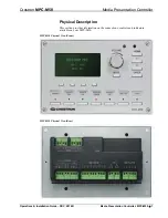
Страница 11: ...cal Description This section provides information on the connections controls and indicators available on your MPC M50 MPC M50 Physical View Front MPC M50 Physical View Rear Operations Installation Guide DOC 6814B Media Presentation Controller MPC M50 7 ...

Страница 12: ...ont View 4 50 in 114 mm 6 70 in 170 mm 2 1 3 4 7 6 5 8 9 10 11 12 13 14 MPC M50 Overall Dimensions Rear and Side Views 0 95 in 24 mm 2 60 in 66 mm 1 90 in 48 mm 2 23 in 57 mm 16 16 15 17 18 19 20 21 8 Media Presentation Controller MPC M50 Operations Installation Guide DOC 6814B ...

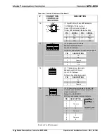
Страница 13: ...er hard key 7 HARD KEYS 7 Programmable buttons with backlit labeling 8 HOME 1 Push button returns to the home page 9 2 Push buttons scroll up or down through menu and adjust menu parameters 10 ENTER 1 Push button executes highlighted menu or value 11 MUTE 1 Programmable push button 12 COMPUTER Pin 2 Pin 3 Pin 1 Pin 4 1 USB Type B female behind front cover USB 1 1 computer console port PIN DESCRIPT...

Страница 14: ... k baud Hardware and software handshaking support PIN DESCRIPTION 1 TX 2 RX 3 Ground 4 RTS 5 CTS 18 COM 2 2 Captive screw terminals Bidirectional RS 232 port Up to 115 2 k baud Software handshaking support PIN DESCRIPTION 1 TX 2 RX 3 Ground 19 RELAYS 1 6 One group of three shown 9 Captive screw terminals comprising 6 normally open isolated relays every two share a common Rated 1 A 30 VAC DC MOV ar...

Страница 15: ...erminals comprising 4 digital or analog input ports referenced to GND Digital input Rated for 0 24 VDC Input impedance 20 kΩ Logic threshold 1 25 VDC Analog input Rated for 0 10 VDC Protected to 24 VDC maximum Input impedance 20 kΩ Programmable 5 V 2 kΩ pull up resistor per pin PIN DESCRIPTION 1 1 2 2 3 3 4 4 5 Ground To determine which is pin 1 on the cable hold the cable so the end of the eight ...

Страница 16: ...e www crestron com manuals Identity Code Net ID The Net ID of the MPC M50 has been factory set to 02 This Net ID is defined as the Master control system The Net IDs of multiple MPC M50 devices in the same system must be unique this means there will be a master slave relationship between units only the Net ID of the master will be left at 02 Net IDs are changed from a personal computer PC via Crest...

Страница 17: ... 2 Btn Head 2021395 or 2021396 4 Prod tool 1 16 Allen Wrench L Key 2022867 1 2021395 with black models 2021396 with white models Installation The following material and tools are required for installation of an MPC M50 Standard 3 gang electrical box not included Philips screwdriver 1 16 Allen wrench included After the wiring has been installed and verified use the following procedure to install th...

Страница 18: ...nded 4 Attach cables to the rear of the MPC M50 Refer to Hardware Hookup which starts on page 16 5 Use the two included 04 40 x 1 4 screws to attach the MPC M50 to the mounting plate CAUTION Excess wire that is pinched between the MPC M50 and the electrical box could short out Make sure that all excess wire is completely inside the electrical box and not between the box and the MPC M50 14 Media Pr...

Страница 19: ...ate positions on the MPC M50 8 Perform any necessary programming using the COMPUTER USB connection prior to attaching the front panel of the MPC M50 Programming can also be performed via the LAN port 9 Remove the protective coating that covers the LCD display 10 Use the four included 04 40 x 1 2 screws and the included 1 16 Allen wrench to attach the front panel to the MPC M50 Operations Installat...

Страница 20: ...r after all connections have been made When making connections to the MPC M50 use Creston power supplies for Crestron equipment NOTE When connecting the included power supply to the NET connector on the unit make sure the lead with the white stripes goes to the terminal marked 24 The other lead goes to the terminal marked G NOTE Ensure the unit is properly grounded by connecting the flying ground ...

Страница 21: ...LAN 10 100Base T Ethernet to LAN or Web COM To any RS 232 Device RELAYS To Controllable Devices IR To IRP2 or Serial Devices INPUTS From Digital or Analog Devices INPUT Connections Depending on the application the MPC M50 INPUTS can be wired multiple ways Refer to the following diagrams when wiring INPUTS CAUTION Incorrect wiring may damage the MPC M50 Operations Installation Guide DOC 6814B Media...

Страница 22: ...m a switch or relay Digital Input Pull up Resistor Disabled 24 VDC Max 1 2 3 4 G Input Wiring Diagrams Analog Input Function Reading a voltage from an analog source Analog Input Pull up Resistor Disabled 10 VDC 1 2 3 4 G Reading resistance of a potentiometer Analog Input Pull up Resistor Enabled 1 2 3 4 G Label the Buttons Optional custom engraved labels for the MPC M50 can be ordered separately b...

Страница 23: ...provides an assortment of Windows based software tools to develop a customized system Use Crestron SystemBuilder or SIMPL Windows to create a program to control the MPC M50 Programming with Crestron SystemBuilder The MPC Wizard in Crestron SystemBuilder is the easiest method of programming the MPC M50 For additional details download SystemBuilder from the Crestron Web site and examine the extensiv...

Страница 24: ...p file F1 Push Button Programming The four soft key push buttons and seven hard key push buttons are programmable and can provide tactile control of many functions such as power source selection transport control audio settings lighting and more Refer to the following illustration for their assigned join numbers A description for each button signal is described in the SIMPL Windows help file F1 MP...

Страница 25: ...tion Use Crestron Toolbox for communicating with the MPC M50 refer to the Crestron Toolbox help file for details There are two methods of communication USB NOTE Required for initial setup of Ethernet parameters NOTE Required for loading projects and firmware USB Communication USB PC Running Crestron Toolbox MPC M50 The COMPUTER port on the MPC M50 connects to the USB port on the PC via a Type A to...

Страница 26: ...using the MPC M50 as a slave edit the master control system s IP table to include an entry for the MPC M50 The entry should list the MPC M50 s IP ID specified on the MPC M50 s IP table and its IP address Programs and Firmware Program or firmware files may be distributed from programmers to installers or from Crestron to dealers Firmware upgrades are available from the Crestron Web site as new feat...

Страница 27: ...s Press SW R behind front cover and HW R buttons at the same time to bypass program and communicate directly with the processor Refer to Troubleshooting Communications in the latest version of the Crestron 2 Series Control Systems Reference Guide Doc 6256 for more details Cresnet device does not respond Device not wired correctly Verify Cresnet wiring Improper Net ID used Verify that device ID mat...

Страница 28: ...to the PC using a USB cable NOTE If your PC does not have the USB driver installed after connecting the MPC M50 to the PC using the USB cable you will see a dialog box on your PC screen asking you to install the USB driver For instructions on how to install the USB driver refer to the Crestron Toolbox help file 5 Open Toolbox and start the Text Console click the icon Then click on the Address Book...

Страница 29: ...lar Cresnet run the wire gauge and the Cresnet power usage of each network unit to be connected must be taken into consideration Use Crestron Certified Wire only If Cresnet units are to be daisy chained on the run the Cresnet power usage of each network unit to be daisy chained must be added together to determine the Cresnet power usage of the entire chain If the unit is home run from a Crestron s...

Страница 30: ... TITLE 2 Series Control Systems Reference Guide Crestron e Control Reference Guide Further Inquiries If you cannot locate specific information or have questions after reviewing this guide please take advantage of Crestron s award winning customer service team by calling Crestron at 1 888 CRESTRON 1 888 273 7876 For assistance in your region please refer to the Crestron Web site www crestron com fo...

Страница 31: ...data or instructions from or to another computer b for local campus or wide area network internet or web hosting services or c pursuant to any rental sharing or service bureau arrangement The Software is designed as a software development and customization tool As such Crestron cannot and does not guarantee any results of use of the Software or that the Software will operate error free and You ack...

Страница 32: ...90 days from the date of receipt and b that any hardware accompanying the Software will be subject to its own limited warranty as stated in its accompanying written material Crestron shall at its option repair or replace or refund the license fee for any Software found defective by Crestron if notified by you within the warranty period The foregoing remedy shall be your exclusive remedy for any cl...

Страница 33: ...lt heads and power supplies are covered for a period of one 1 year touchscreen display and overlay components are covered for 90 days batteries and incandescent lamps are not covered This warranty extends to products purchased directly from CRESTRON or an authorized CRESTRON dealer Purchasers should inquire of the dealer regarding the nature and extent of the dealer s warranty if any CRESTRON shal...

Страница 34: ...Media Presentation Controller Crestron MPC M50 This page is intentionally left blank 30 Media Presentation Controller MPC M50 Operations Installation Guide DOC 6814B ...

Страница 35: ...Crestron MPC M50 Media Presentation Controller This page is intentionally left blank Operations Installation Guide DOC 6814B Media Presentation Controller MPC M50 31 ...

Страница 36: ...ron Electronics Inc Operations Installation Guide DOC 6814B 15 Volvo Drive Rockleigh NJ 07647 2024142 Tel 888 CRESTRON 04 11 Fax 201 767 7576 Specifications subject to www crestron com change without notice ...

Отзывы: