background image

Wall Plate DigitalMedia™ CAT Transmitters  

Crestron 

DM-TX-200-2G/400-3G 

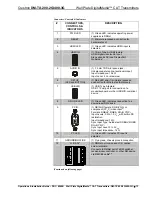
Connectors, Controls & Indicators (Continued) 

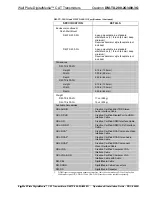
# CONNECTORS, 

CONTROLS & 

INDICATORS 

DESCRIPTION 

13 M 


(1) DM CAT output composed of (8) captive 
screw terminals with (1) grounded strain 
relief; 
Connects to DM CAT input of a DM switcher, 
receiver/room controller or other DM device 
via the yellow “M” cable of DM-CBL cable

5

Uses the 568-B wiring standard. 

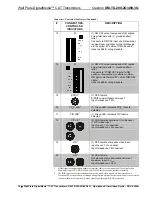
14 


(1) DM CAT output composed of (8) captive 
screw terminals with (1) grounded strain 
relief; 
Connects to “D” DM CAT input of a DM 
switcher, receiver/room controller or other 
DM device via the blue “D” cable of DM-CBL 
cable

5

Uses the 568-B wiring standard. 

15 SPDIF

7


(1) RCA female; 
S/PDIF coaxial digital audio input; 
Input Impedance: 75 


16 

YP

b

P

r


LED

7


(1) Green LED, indicates YP

b

P

r

 input is 

selected 

17 VID 

LED

7


(1) Green LED, indicates VID input is 
selected 

18 

Y, P

b

, P

r

7


(3) RCA female comprising (1) component 
(YP

b

P

r

) video input; 

Input Level: 1 V

p-p

 nominal; 

Input Impedance: 75 

 nominal 

19 VID

7


(1) RCA female, composite video input; 
Input Level: 1 V

P-P

 nominal; 

Input Impedance: 75 

 nominal 

20 

L, R

7


(2) RCA female; 
Unbalanced stereo line-level audio input; 
Maximum Input: 2 V

rms

Input Impedance: 15k 


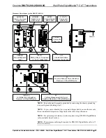
1.


HDMI requires an appropriate adapter or interface cable to accommodate a DVI or DisplayPort 
Multimode signal. CBL-HD-DVI and CBL-DP-HD interface cables available separately. 

2.


The RGB input can accept component, composite, and S-video signals via direct interface to 
Crestron MPS Series products, or through an appropriate adapter (not included). Input sync detection 
is not provided for composite or S-video signal types through the RGB connection. 

14  

  Wall Plate DigitalMedia™ CAT Transmitters: DM-TX-200-2G/400-3G  Operations & Installation Guide – DOC. 6949B 

Содержание DigitalMedia DM-TX-200-2G

Страница 1: ...Crestron DM TX 200 2G 400 3G WallPlateDigitalMedia CAT Transmitters Operations Installation Guide...

Страница 2: ...ance with the instructions may cause harmful interference to radio communications However there is no guarantee that interference will not occur in a particular installation If this equipment does cau...

Страница 3: ...up 23 Programming Software 26 Earliest Version Software Requirements for the PC 26 Programming with Crestron SystemBuilder 26 Programming with SIMPL Windows 26 Uploading and Upgrading 29 Establishing...

Страница 4: ......

Страница 5: ...timedia interface Built in 2x1 DM TX 200 2G or 4x1 DM TX 400 3G AV switcher DM CAT output supports up to 450 foot 137 meter cable length1 2 gang DM TX 200 2G or 3 gang DM TX 400 3G wall mount design A...

Страница 6: ...ess audio The HDMI input can also handle DVI and DisplayPort Multimode signals using an appropriate adapter or dongle2 The RGB input handles all analog RGB signals up to WUXGA 1920x1200 pixels as well...

Страница 7: ...control wires or IR probes Through proper CEC signal management DigitalMedia allows you to take control of each device in the system as you like Simple Wall Mount Design The DM TX 200 2G and DM TX 400...

Страница 8: ...00 3G Applications The following diagram shows a DM TX 200 2G and a DM TX 400 3G in a typical application DM TX 200 2G and DM TX 400 3G in a Typical Application 4 Wall Plate DigitalMedia CAT Transmitt...

Страница 9: ...up to 1080p60 NTSC or PAL Input Resolutions HDMI DVI Progressive 640 x 480 60 Hz 720 x480 60 Hz 480p 720 x 576 50 Hz 576p 800 x 600 60 Hz 848 x 480 60 Hz 852 x 480 60 Hz 854 x 480 60 Hz 1024 x 768 60...

Страница 10: ...x 720 60 Hz 720p60 1280 x 768 60 Hz 1280 x 800 60 Hz 1280 x 960 60 Hz 1280 x 1024 60 Hz 1360 x 768 60 Hz 1366 x 768 60 Hz 1400 x 1050 60 Hz 1440 x 900 60 Hz 1600 x 1200 60 Hz 1680 x 1050 60 Hz 1920 x...

Страница 11: ...nalog To Digital Conversion 24 bit 48 kHz Performance Analog Frequency Response 20 Hz to 20 kHz 0 75 dB S N Ratio 90 dB 20 Hz to 20 kHz A weighted THD N 0 05 1 kHz Stereo Separation 90 dB Communicatio...

Страница 12: ...tron Certified Mini TRS Stereo Audio Interface Cable CBL DP HD Crestron Certified DisplayPort to HDMI Interface Cable CBL HD Crestron Certified HDMI Interface Cable CBL HD DVI Crestron Certified HDMI...

Страница 13: ...TX 400 3G only NOTE Crestron software and any files on the Web site are for authorized Crestron dealers and Crestron Authorized Independent Programmers CAIP only New users may be required to register...

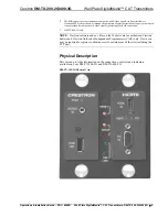
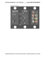
Страница 14: ...Wall Plate DigitalMedia CAT Transmitters Crestron DM TX 200 2G 400 3G DM TX 400 3G Physical View 10 Wall Plate DigitalMedia CAT Transmitters DM TX 200 2G 400 3G Operations Installation Guide DOC 6949B...

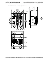
Страница 15: ...0 2G Overall Dimensions Front Right Rear Views 3 50 in 89 mm 4 12 in 105 mm 3 37 in 86 mm 2 63 67 mm 2 53 in 64 mm 2 00 in 51 mm 0 34 in 9 mm 6 7 1 5 8 2 4 9 3 11 13 10 12 14 Operations Installation G...

Страница 16: ...Dimensions Front Right Rear Views 5 30 in 135 mm 4 12 in 102 mm 0 34 in 9 mm 2 53 in 64 mm 2 00 in 51 mm 2 63 in 67 mm 5 18 in 132 mm 6 7 1 5 8 2 4 9 3 11 13 10 12 14 17 19 15 18 20 16 12 Wall Plate...

Страница 17: ...HID 1 USB Type A female USB 1 1 host port for connection of a mouse keyboard or other USB HID compliant device 8 DM LINK LED 1 Green LED indicates connection to a downstream DM device 9 PC IN 1 DB15H...

Страница 18: ...cates YPbPr input is selected 17 VID LED 7 1 Green LED indicates VID input is selected 18 Y Pb Pr 7 3 RCA female comprising 1 component YPbPr video input Input Level 1 Vp p nominal Input Impedance 75...

Страница 19: ...A 24 connector pinouts G B A 24 PIN SIGNAL DESCRIPTION WIRE COLOR G Ground DC Ground Black B DMNet DMNet Grey A DMNet DMNet Orange 24 24V DC DC Power Red 5 For DigitalMedia CAT wiring use DM CBL Digit...

Страница 20: ...Check Network Wiring on page 34 Identity Code NOTE In the SIMPL Windows program when a DM TX 200 2G or DM TX 400 3G is dropped onto an input card of a DM switcher its IP ID is assigned automatically...

Страница 21: ...2x RCA analog input 1 Audio will be transmitted from the 3 5 mm mini TRS phone input based on the presence of a connector in the jack 2 DM TX 400 3G only 3 If no audio signal is present the default a...

Страница 22: ...1 2 inches 64 mm deep minimum It is assumed that the required cable has been fed through an installed 2 gang or 3 gang electrical box not supplied and wiring has been verified 1 Confirm that DMNet sys...

Страница 23: ...D Cable Wrapping the Twisted Braid 7 Strip the insulation from the ends of each wire exposing approximately 3 16 inch 5 mm of bare copper NOTE Do not allow the twisted pairs to untwist for more than 1...

Страница 24: ...river not supplied make the connections as specified using the labels on the unit as a guide a Insert the twisted pairs of the gray DMNet cable into the G B A 24 terminal block and tighten each screw...

Страница 25: ...l box the electrical box must be earth grounded 13 Attach the unit to the electrical box using the included 06 32 x 3 4 oval head slotted screws as shown in the illustration on the following two pages...

Страница 26: ...ew Wall Plate with Hardware Not Supplied Screws 4 06 32 x 3 4 Truss Combo Head 2009211 Ground Wire D Cable M Cable 2 Gang Wall Box Not Supplied Data Control Cable Assy DM TX 200 2G Module 6503588 or 6...

Страница 27: ...d out in the illustration that follows this paragraph Refer to Network Wiring on page 16 before attaching the DMNet Cable Apply power after all connections have been made When making connections to th...

Страница 28: ...t USB HID Mouse Keyboard Input PC IN RGB VGA or Component Y Pb Pr Video Input Ground G B A 24 To DMNet Port of Switcher Receiver or Other DM Device M To Data Management M Port of Switcher Receiver or...

Страница 29: ...Port of Switcher Receiver or Other DM Device D To Video Data D Port of Switcher Receiver or Other DM Device Ground NOTE Ensure the unit is properly grounded by connecting the chassis ground lug to an...

Страница 30: ...iest method of programming but does not offer as much flexibility as SIMPL Windows For additional details download SystemBuilder from the Crestron Web site and examine the extensive help file Programm...

Страница 31: ...card in a DM MD8X8 switcher both sold separately In the second example the DM TX 200 2G and DM TX 400 3G is used with the C2ENET 2 card sold separately in an Ethernet slot on the control system C2ENET...

Страница 32: ...ed in the SIMPL Windows program must match the IP ID of each unit Refer to Identity Code on page 16 Program Manager Program Manager is the view where programmers program a Crestron control system by a...

Страница 33: ...communication than USB Via a DM RMC 100 using TCP IP communication Via DM Switcher TCP IP Communication via DM Switcher ETHERNET DM Switcher PC Running Crestron Toolbox LAN DM TX 200 2G or DM TX 400...

Страница 34: ...gh a hub or router use CAT5 straight through cables with 8 pin RJ 45 connectors Alternatively use a CAT5 crossover cable to connect the two LAN ports directly without using a hub or router 2 By defaul...

Страница 35: ...d the IP address of the DM TX 200 2G or DM TX 400 3G 2 Add the IP address to the Address Book in Toolbox 3 Download the appropriate puf file from the Crestron Web site to your PC 4 Double click the pu...

Страница 36: ...DM TX 200 2G or DM TX 400 3G Then display the System Info window click the icon and select the DM TX 200 2G or DM TX 400 3G entry from the Address Book 2 Select Functions IP Table Setup 3 Add modify o...

Страница 37: ...Device is not receiving sufficient power Use the Crestron Power Calculator to help calculate how much power is needed for the system PWR LED does not illuminate Device is not receiving power Verify th...

Страница 38: ...repeaters Please use the DMNet Power Calculator to help calculate how much power is needed for the system www crestron com calculators Refer to the following table for commonly used resolutions and m...

Страница 39: ...also log onto the online help section of the Crestron Web site www crestron com onlinehelp to ask questions about Crestron products First time users will need to establish a user account to fully ben...

Страница 40: ...t heads and power supplies are covered for a period of one 1 year touchscreen display and overlay components are covered for 90 days batteries and incandescent lamps are not covered This warranty exte...

Страница 41: ...erstands that there is no warranty for this free software If the software is modified by someone else and passed on we want its recipients to know that what they have is not the original so that any p...

Страница 42: ...gram or a work based on it under Section 2 in object code or executable form under the terms of Sections 1 and 2 above provided that you also do one of the following a Accompany it with the complete c...

Страница 43: ...opyright holder who places the Program under this License may add an explicit geographical distribution limitation excluding those countries so that distribution is permitted only in or among countrie...

Страница 44: ...on Electronics Inc Operations Installation Guide DOC 6949B 15 Volvo Drive Rockleigh NJ 07647 2027115 Tel 888 CRESTRON 02 11 Fax 201 767 7576 Specifications subject to www crestron com change without n...

Отзывы: