background image

Power Supply for Crestron

®

 Shades  

Crestron 

CSA-PWS300/600-CAEN


Installation Guide – DOC. 7407A 

Power Supply for Crestron

®

 Shades:  CSA-PWS300/600-CAEN  

  7  


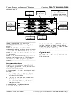
Device Wiring Details 


NOTE:  

Always disconnect AC power to the  

CSA-PWS300/600-CAEN before connecting network 

devices.  

NOTE:  

Install the four-position terminal block 

connectors as shown. The CSA-PWS300-CAEN has eight 

connectors. The CSA-PWS600-CAEN has 16 connectors. 

NOTE:

  Only eight network devices should be connected 

to a power supply. 

NOTE:

  On the CSA-PWS600-CAEN, jump a wire from 

each pin on the lower power supply’s 

NET

 connector to 

the respective pin on the upper power supply’s 

NET


connector. 

Maximum Wire Runs 

Length between motor and power supply is limited by 

voltage drop along cable. The following limits should be 

observed for reliable performance. 
Maximum length of Cresnet cable between power supply 

and shade: 


Cresnet-P (Plenum Rated, 2x #18 Power, 2x #22 

Twisted Data) 130 ft (~40 m) 


Cresnet-NP (2x #18 Power, 2x #22 Twisted Data) 

130 ft (~40 m) 


Cresnet-HP-NP (2x #12 Power, 2x #22 Twisted 

Data) 500 ft (~153 m) 

Maximum total length of Cresnet cable run on 

network/Hub: 3000 ft (~915 m) 


Use of a Cresnet Hub/Repeater (CNXHUB) is advised 

whenever the number of Cresnet devices on a network 

exceeds 20 or when the combined total length of Cresnet 

cable exceeds 3000 feet (914 meters). 

Operation 

The switch on the left side of each supply must be in the 

PWR ON

 position. 


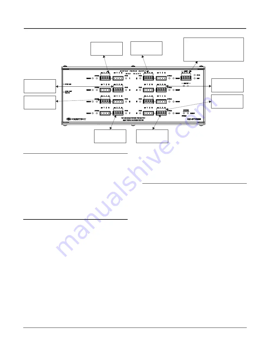
NET:

From Control System;

To Second Power Supply

(CSA-PWS600-CAEN Only)

1:

To Shade # 1

2:

To Shade # 2

3:

To Shade # 3

4:

To Shade # 4

5:

To Shade # 5

6:

To Shade # 6

7:

To Shade # 7

8:

To Shade # 8

Содержание CSA-PWS300-CAEN

Страница 1: ...ying an external 24V DC signal to the NET port Reset 1 8 8 Miniature push buttons each resets its respective output channel or momentarily disables the channel while held System Reset 1 Miniature push button resets all output channels sequentially or momentarily disables all channels while held Setup Not used LED Indicators PWR 1 8 8 Green LEDs indicate 24 VDC power present at each channel output ...

Страница 2: ... and found to comply with the limits for a Class B digital device pursuant to part 15 of the FCC Rules These limits are designed to provide reasonable protection against harmful interference in a residential installation This equipment generates uses and can radiate radio frequency energy and if not installed and used in accordance with the instructions may cause harmful interference to radio comm...

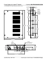
Страница 3: ...32 in 156 mm 2 1 2 in 64 mm 1 2 14 mm TYP 1 7 16 in 37 mm 1 in 26 mm 7 3 4 in 197 mm 7 3 4 in 197 mm 6 5 32 in 156 mm Qty 2 Ø 1 3 4 in 44 mm Knockouts Ø 7 8 in 22 mm Knockouts for 1 2 13 mm conduit Typ 16 3 32 in 409 mm 4 5 16 in 110 mm 2 13 32 in 61 mm 1 5 32 in 61 mm 15 16 in 24 mm 1 1 4 in 32 mm 4 3 32 in 104 mm 2 1 2 in 64 mm 1 1 8 in 29 mm 14 11 32 in 364 mm 4 in 102 mm Qty 12 Ø 3 16 in 5 mm ...

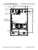
Страница 4: ...ion Guide DOC 7407A CSA PSW300 CAEN Overall Dimensions without Front Cover Qty 4 Ø 5 16 8 mm Mounting Holes Qty 4 Ø 5 8 16 mm Mounting Holes Install Cresnet Connectors as Shown 8 Outputs Maximum for each Power Supply Barcode Label Ground Bus 10 27 32 in 275 mm 1 3 4 in 45 mm 2 5 32 in 55 mm 9 32 in 7 mm Typ 18 19 32 in 472 mm ...

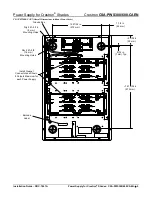
Страница 5: ...A PWS300 600 CAEN 5 CSA PSW600 CAEN Overall Dimensions without Front Cover 10 27 32 in 275 mm 1 3 4 in 45 mm 2 5 32 in 55 mm 9 32 in 7 mm Typ 18 19 32 in 472 mm Qty 4 Ø 5 16 8 mm Mounting Holes Qty 4 Ø 5 8 16 mm Mounting Holes Install Cresnet Connectors as Shown 8 Outputs Maximum for each Power Supply Barcode Label Ground Bus ...

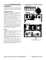
Страница 6: ...The CSA PWS300 600 CAEN attaches to a mounting surface using four standard screws appropriate for the mounting scenario Once the unit is properly secured to the mounting surface the units must be properly wired Refer to Wiring below for details Wiring CAUTION All power feeds must be protected by 15 or 20 Amp circuit breakers not supplied NOTE Use copper conductors only rated 60 C NOTE All wiring m...

Страница 7: ...nd power supply is limited by voltage drop along cable The following limits should be observed for reliable performance Maximum length of Cresnet cable between power supply and shade Cresnet P Plenum Rated 2x 18 Power 2x 22 Twisted Data 130 ft 40 m Cresnet NP 2x 18 Power 2x 22 Twisted Data 130 ft 40 m Cresnet HP NP 2x 12 Power 2x 22 Twisted Data 500 ft 153 m Maximum total length of Cresnet cable r...

Страница 8: ...ncur additional charges if support is required to identify performance deficiencies because of using improper wire Calculate Power CAUTION Use only Crestron power supplies for Crestron equipment Failure to do so could cause equipment damage or void the Crestron warranty CAUTION Provide sufficient power to the system Insufficient power can lead to unpredictable results or damage to the equipment Us...

Страница 9: ...ds 20 or when the combined total length of Cresnet cable exceeds 3000 feet 914 meters Further Inquiries To locate specific information or resolve questions after reviewing this guide contact Crestron s True Blue Support at 1 888 CRESTRON 1 888 273 7876 or refer to the listing of Crestron worldwide offices on the Crestron Web site www crestron com offices for assistance within a particular geograph...

Страница 10: ... directly from Crestron or an authorized Crestron dealer Purchasers should inquire of the dealer regarding the nature and extent of the dealer s warranty if any Crestron shall not be liable to honor the terms of this warranty if the product has been used in any application other than that for which it was intended or if it has been subjected to misuse accidental damage modification or improper ins...

Отзывы: