background image

Antenna System  

Crestron 

SRD-ANT-4-PAK


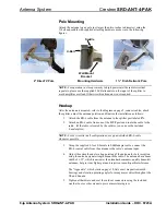
Pole Mounting  

Attach the antenna to any pole (not larger than two inches in diameter) using the  
U-bolt and saddle with supplied attaching hardware as shown in the following 
figures. 


U-Bolt

Wall Mount

Bracket 

Mounting Hardware 

 2” DirecTV Pole 

Saddle

1 ¾” Dish Network Pole 

NOTE:

 For operation in close proximity to high power satellite radio terrestrial 

repeaters, please use the supplied 20 dB attenuator on the input of the splitter to 
avoid amplifier overload. Otherwise this attenuator is not required. 

Hookup  

After the antenna is mounted, refer to the diagram on page 2, connect cables, attach 
the splitter, adjust the antenna position, and finalize the installation as follows: 

1.  Attach the RG-6 cable from the antenna to the splitter port labeled 

IN

.   

2.  Attach an RG-6 cable from one of the 

OUT

 ports and route the cable to the 

radio.  (If the radio is located by the splitter, you can use the included  
F-male splice). 

NOTE:

 For best results in all configurations, use quad-shielded RG-6 cable 

whenever possible. 

3.  Using the supplied 3-foot F-Female to SMB adapter cable, connect the  

RG-6 coaxial cable from the antenna to the radio’s antenna input. 

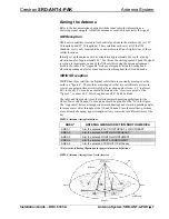
4.  Adjust the azimuth and elevation pointing of the antenna for best reception 

using the antenna signal strength menu in the radio. The antenna has a beam 
width of ± 25º, which is narrower than standard consumer-quality home-kit 
antennas, but provides higher gain and rejection to multi-path interference.  
 
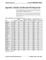
The “Appendix”, which starts on page 10, lists exact magnetic azimuth 
bearings and elevation pointing angles for many major cities throughout the 
US and Canada.  

5.  Tighten all hardware and seal the outdoor connectors using the included 

weather boot or other means to prevent moisture ingress.  

6  

  Antenna System: SRD-ANT-4-PAK 

Installation Guide – DOC. 6723A 

Содержание Antenna System SRD-ANT-4-PAK

Страница 1: ...Crestron SRD ANT 4 PAK Antenna System Installation Guide...

Страница 2: ...rmation with regard to proper grounding of the mast and supporting structure grounding of the lead in wire to an antenna discharge unit size of grounding conductors location of antenna discharge unit...

Страница 3: ...4 Installation 5 Installation Notes 5 Wall Mounting 5 Pole Mounting 6 Hookup 6 Aiming the Antenna 7 Problem Solving 8 Troubleshooting 8 Further Inquiries 8 Future Updates 9 Appendix Azimuth and Eleva...

Страница 4: ......
Страница 5: ...installation of the antenna to any horizontal or vertical flat surface The additional U bolt and saddle enable mounting to a pole not included up to two inches in diameter Connections between the ante...

Страница 6: ...ATION DETAILS Antenna Gain Polarization Output connector Wind resistance 12dBi Typical Left hand circular F female Up to 100 MPH Splitter Gain at 2 335 GHz Max noise figure Max input signal Current co...

Страница 7: ...s The items included in the SRD ANT 4 PAK are listed in the following table and illustrated on the following page SRD ANT 4 PAK Included Items DESCRIPTION PART NUMBER QTY Satellite Radio Antenna SRD A...

Страница 8: ...d Items Industry Compliance As of the date of manufacture the SRD ANT 4 PAK has been tested and found to comply with specifications for CE marking and standards per EMC and Radiocommunications Complia...

Страница 9: ...ith no signal loss For longer cable runs use in line amplifier s SRD AMP 1 purchased separately to boost the signal Although this antenna can receive signals from terrestrial repeaters it is recommend...

Страница 10: ...one of the OUT ports and route the cable to the radio If the radio is located by the splitter you can use the included F male splice NOTE For best results in all configurations use quad shielded RG 6...

Страница 11: ...the earth in a figure 8 These orbits are arranged so that two satellites are always in view at any point in time at relatively high elevation angles from 45 to almost 90 in the sky Your antenna should...

Страница 12: ...labeled Radio oriented towards the radio No signal reception Radio display shows Antenna Disconnected or Acquiring Signal Check Antenna or No Signal Antenna is connected properly but signal is too we...

Страница 13: ...ade available as manual updates These updates are solely electronic and serve as intermediary supplements prior to the release of a complete technical documentation revision Check the Crestron website...

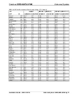
Страница 14: ...1 119 8 36 3 161 2 48 4 San Diego CA 45 7 61 4 120 6 38 0 163 4 50 0 San Francisco CA 58 5 58 3 116 4 30 6 153 8 43 5 Denver CO 43 8 77 6 142 4 37 9 184 4 40 8 Washington DC 300 0 65 7 202 5 42 1 239...

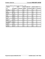
Страница 15: ...New York NY 295 9 63 0 208 8 39 4 243 7 26 2 Cleveland OH 294 6 71 8 192 6 39 7 230 1 30 0 Tulsa OK 352 6 78 4 158 8 44 6 203 8 41 9 Burns OR 67 9 63 4 121 9 27 9 158 4 37 3 Eugene OR 69 0 58 9 117 1...

Страница 16: ...ON 287 9 69 8 198 6 39 3 236 5 28 4 Ottawa ON 282 6 65 6 204 0 36 9 240 1 25 1 Montreal QB 286 3 63 2 210 9 36 4 246 1 23 8 St Johns QB 286 8 62 8 211 5 36 6 246 6 23 7 Halifax NS 290 7 51 7 227 8 34...

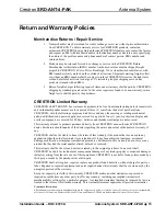
Страница 17: ...90 days batteries and incandescent lamps are not covered This warranty extends to products purchased directly from CRESTRON or an authorized CRESTRON dealer Purchasers should inquire of the dealer re...

Страница 18: ...Antenna System Crestron SRD ANT 4 PAK This page is intentionally left blank 14 Antenna System SRD ANT 4 PAK Installation Guide DOC 6723A...

Страница 19: ...Crestron SRD ANT 4 PAK Antenna System This page is intentionally left blank Installation Guide DOC 6723A Antenna System SRD ANT 4 PAK 15...

Страница 20: ...Crestron Electronics Inc Installation Guide DOC 6723A 15 Volvo Drive Rockleigh NJ 07647 2021911 Tel 888 CRESTRON 08 08 Fax 201 767 7576 Specifications subject to www crestron com change without notice...

Отзывы: