background image

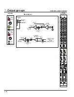
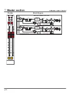
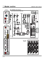
MATRIX 1 (2) - LOCATED ON MASTER 1 (2)

( MATRIX 1 SHOWN, MATRIX 2 IS IDENTICAL )

OUT 13

MATRIX 3 (4)

MIX AMP

MATRIX
INSERT

SEND     RTN

MATRIX

INST RTN

TO EQ 3 (4)

ALWAYS ON

MATRIX PATH

MATRIX

PRE-FADER

MATRIX

MUTE

OUT 14

OUT 15

OUT 16

MATRIX

EXT IN

MIX 15 (16)

MIX AMP

MATRIX

PRE-FADER

MATRIX

POST-FADER

MATRIX 3 (4)

TO A (B)

MATRIX TALKBACK
(FROM MASTER 2)

MATRIX 3 (4) - LOCATED ON MASTER 3 (4)

( MATRIX 3 SHOWN, MATRIX 4 IS IDENTICAL )

ALLOWS MATRIX 3 AND 4

TO BE ADDED INTO

MIX A AND B

TO MIX A (B)

TO MATRIX MIXES

MATRIX 3 & 4 HAVE DEDICATED

EQS, AND THE MATRIX

OUTPUTS CAN BE ADDED

INTO MIXES A AND B

MIX

15 (16)

OUT

15 (16)

5-BAND EQ

MUTE AND SOLO SWITCHING

(MICRO CONTROLLED)

TO SOLO BUS & MICRO INTERFACE

GC

EXT IN

FROM MIX A (B)

INSERT RETURN

LEV

FR

LEV

FR

LEV

FR

LEV

FROM MATRIX 1 (2)

INSERT RETURN

5-BAND EQ - NORMALLY ON MATRIX PATH

( 1 OF 4 SHOWN )

FROM MATRIX 3 (4)

INSERT RETURN

PATH SWITCHING BETWEEN
MATRIX AND MAIN MIX ONLY

AVAILABLE ON EQ 1 & 2

FIVE BAND EQ (1 OF 4)

LEV

MID

HI MID

HF

FR

LO MID

400 TO 8K

200 TO 4K

100 TO 2K

12K

LF

20 TO 400

EQ
ON

EQ TO

MIX A (B)

TO MIX A (B)

PRE-FADER

TO MATRIX 1 (2)

PRE-FADER

TO MATRIX 3 (4)

PRE-FADER

PATH SWITCHING BETWEEN
MATRIX AND MAIN MIX ONLY

AVAILABLE ON EQ 1 & 2

+10

MATRIX 3 (4)

BAL OUT

MATRIX

LEVEL

MATRIX

POST-FADER

MUTE

SOLO

p. 32

3

Master Section

X-Monitor owner’s manual 

Содержание X-Monitor

Страница 1: ...Owner s Manual S E R I E S X Monitor Mixing Console ...

Страница 2: ...ell boost shelf cut freq center 80Hz Q 7 on boost high pass filter 12dB octave freq range 20Hz 400Hz separate on switches for eq and high pass filter five band eq on all main outputs high pass filter 12dB octave freq range 20Hz 400Hz separate on switches for eq and high pass filter five segment LED ladder with VU type response displays pre fader signal level top red LED warns of impending overload...

Страница 3: ...1 3 4 master section p 28 microprocessor control p 48 2 group module p 20 mono input module p 6 Mic and line inputs 5 power supply p 66 p 3 Table of contents ...

Страница 4: ...CAL RTN MUTE SAFE PREVIEW SAFE PREVIEW X MONITOR MASTER MODULE UPPER AREA MIX AMP A FROM MASTER MICRO CARD TO INPUT MICRO CARDS 9 10 LEV PAN CTRL HPF HPF 20 400HZ MUTE SOLO AND STEREO CTRL SIGNAL PRESENT PEAK GROUP FADER AMP GRP PRE FADER STEREO PAIR GRP STEREO CTRL SW ON ODD GRP LED ON EVEN GRP GROUP PRE FDR POST FDR COMMON RTN MUTE SAFE PREVIEW LEV PAN CTRL TO INPUTS WHEN SELECTED FOR STEREO PAI...

Страница 5: ... needed for getting the most out of the X Monitor console a flexible and feature rich addition to Crest Audio s grow ing line of audio mixing console products Conventions Control Icons This manual uses little pictures or icons to illustrate what the control descriptions are referring to This makes it possible to avoid redundant wording and makes the control descriptions clear Switch in the UP non ...

Страница 6: ...Module Controls Block diagram BALANCED IN INPUT PREAMP GAIN 15 70 DB HPF LINE 26dB PAD 48V XFORMER OPTION HPF 20 400HZ SPLIT OUT LINE SW LINE SW PIN 1 LIFT P Ø p 6 1 Mono input module X Monitor owner s manual ...

Страница 7: ...R mic input connector or the 1 4 TRS input jack both located on the rear panel When a plug is inserted into the 1 4 TRS input jack the XLR mic input connector is disabled Polarity reverse ø This feature is used for correcting or minimizing polarity and phase related errors For example occasionally a balanced input connection is reverse wired before it gets to the mixing console This can happen in ...

Страница 8: ...Module Controls Block diagram BALANCED IN INPUT PREAMP GAIN 15 70 DB HPF LINE 26dB PAD 48V XFORMER OPTION HPF 20 400HZ SPLIT OUT LINE SW LINE SW PIN 1 LIFT P Ø p 8 1 Mono input module X Monitor owner s manual ...

Страница 9: ... at the input XLR and input 1 4 TRS is 20kΩ High pass filter HPF Proper use of the high pass filter reduces or eliminates unwanted low frequencies without substantially affecting the program material Quite often such unwanted low frequencies are included with in coming mic or line input signals For example stage rumble or wind can be picked up through vocal mics The slope of the high pass filter i...

Страница 10: ...HI MID HF HPF X MONITOR INPUT 24 32 OR 40 FITTED HPF 20 400HZ FREQ LEVEL LEVEL FREQ LEVEL 12 KHZ 400 8 KHZ 80 2 KHZ 100 HZ PRE SOURCE SELECT PRE SOUR MUTE 10 EQ ON PEAK FADER AMP PRE SOURCE AMP EQ FDR NO YES 8 0 6 SIG INPUT METER PRE FADER p 10 1 Mono input module X Monitor owner s manual ...

Страница 11: ...ting frequencies An independent variable high pass filter provides additional problem solving flexibility High frequency HF Boost Cut 15dB boost and cut at 12 kHz Shelving eq High mid HM Boost Cut 15dB boost and cut with a Q of 2 Frequency Continuously sweepable between 400 Hz and 8 kHz Low mid LM Boost Cut 15dB boost and cut with a Q of 2 Frequency Continuously sweepable between 100 Hz and 2 kHz ...

Страница 12: ... GROUP SENDS 1 THRU 12 1 4 PRE INPUT CHAN MICRO INTERFACE CARD 1 OF 4 CIRCUITS FROM PREV MODULE TO NEXT MODULE 1 LEV 2 PAN 3 LEV 4 PAN 5 LEV 6 PAN 7 LEV 8 PAN 9 LEV 10 PAN 11 LEV 12 PAN 5 8 PRE 9 12 PRE 1 2 LEV PAN CTRL 3 4 LEV PAN CTRL 5 6 LEV PAN CTRL 7 8 LEV PAN CTRL 11 12 LEV PAN CTRL MUTE AND SOLO CTRL MIX 1 MIX 2 MIX 3 MIX 4 MIX 5 MIX 6 MIX 7 MIX 8 MIX 9 MIX 10 MIX 11 MIX 12 SOLO SAFE PREVIE...

Страница 13: ...end level for the respective mix When stereo mode is selected the top odd numbered control sets signal level while the bottom even numbered control pans the signal between odd and even group buses odd left even right Mix PRE switches 1 4 5 8 9 12 The PRE switches determine the source for the three groups of four MIX sends The sig nal that these switches use for the PRE setting can be further defin...

Страница 14: ... GROUP SENDS 1 THRU 12 1 4 PRE INPUT CHAN MICRO INTERFACE CARD 1 OF 4 CIRCUITS FROM PREV MODULE TO NEXT MODULE 1 LEV 2 PAN 3 LEV 4 PAN 5 LEV 6 PAN 7 LEV 8 PAN 9 LEV 10 PAN 11 LEV 12 PAN 5 8 PRE 9 12 PRE 1 2 LEV PAN CTRL 3 4 LEV PAN CTRL 5 6 LEV PAN CTRL 7 8 LEV PAN CTRL 11 12 LEV PAN CTRL MUTE AND SOLO CTRL MIX 1 MIX 2 MIX 3 MIX 4 MIX 5 MIX 6 MIX 7 MIX 8 MIX 9 MIX 10 MIX 11 MIX 12 SOLO SAFE PREVIE...

Страница 15: ...nd the fader stage Overload at any of these stages will cause the red peak LED to light The channel gain should reduced if this occurs Signal level LEDs These three LEDs light up at 8 yellow 0 green and 6 dB green This level range 6 to 8 is the optimum operating range Compressed or relatively constant signals should remain close to 0 Signal present indicator SIG This green LED varies in brightness...

Страница 16: ... GROUP SENDS 1 THRU 12 1 4 PRE INPUT CHAN MICRO INTERFACE CARD 1 OF 4 CIRCUITS FROM PREV MODULE TO NEXT MODULE 1 LEV 2 PAN 3 LEV 4 PAN 5 LEV 6 PAN 7 LEV 8 PAN 9 LEV 10 PAN 11 LEV 12 PAN 5 8 PRE 9 12 PRE 1 2 LEV PAN CTRL 3 4 LEV PAN CTRL 5 6 LEV PAN CTRL 7 8 LEV PAN CTRL 11 12 LEV PAN CTRL MUTE AND SOLO CTRL MIX 1 MIX 2 MIX 3 MIX 4 MIX 5 MIX 6 MIX 7 MIX 8 MIX 9 MIX 10 MIX 11 MIX 12 SOLO SAFE PREVIE...

Страница 17: ...Groups can be globally switched to Pre fader by using the 13 16 PRE switch located in the Master section A Bus assignment The Input signal is assigned to the mainA output bus This feed is always Post fader B Bus assignment The Input signal is assigned to the main B output bus This feed is always Post fader Input fader The 100mm channel fader is the primary level control for all Post fader signals ...

Страница 18: ...t S e n d R t n I n s e r t Local Rtn 2 2 Group Out S e n d R t n I n s e r t Local Rtn 1 1 Group Out 4 3 2 1 X Monitor Group 5 8 Common Return R C Common Return L S e n d R t n I n s e r t Local Rtn 8 8 Group Out S e n d R t n I n s e r t Local Rtn 7 7 Group Out S e n d R t n I n s e r t Local Rtn 6 6 Group Out S e n d R t n I n s e r t Local Rtn 5 5 Group Out 8 7 6 5 In MIDI Out To Meter Bridge ...

Страница 19: ...nother desk typically a front of house console In most cases this can eliminate the need for a separate splitter box Pin 1 lift When this button is depressed the XLR Mic In and Splitter Out Pin 1 connection is isolated from the chassis ground of the console The Pin 1connection is maintained between the two jacks but is isolated from the mixer ground NOTE When the Pin 1 Lift switch is depressed the...

Страница 20: ...GURED FOR LEV PAN OPERATION ODD IS LEV EVEN IS PAN GROUP SOLO IS CHANGED FROM MONO TO STEREO ODD GRP SOLOS TO LEFT EVEN GRP TO RIGHT MIX 1 TO 12 TB FEED LOCAL RETURN BAL INSERT RTN GROUP RETURN TO EQ 6 LOCAL RTN MUTE LOC RTN POST LOC RTN PRE LEVEL TO GROUP MIX AMP COMMON RETURN 6 COMMON RTN MUTE COM RTN POST LEVEL TO GROUP MIX AMP COMMON RTN FEED L R FROM MASTERS 1 2 LEFT IN RIGHT IN 6 GRP POST FA...

Страница 21: ...nd cut Mid frequencies MF Frequency Continuously sweepable between 200 Hz and 4 kHz Q Bandwidth Continuously variable between 3 and 7 Boost Cut 15dB boost and cut Low mid LM Frequency Continuously sweepable between 100 Hz and 2 kHz Q Bandwidth Continuously variable between 3 and 7 Boost Cut 15dB boost and cut Low frequency LF Frequency Continuously sweepable between 40 Hz and 800 Hz Boost Cut 15dB...

Страница 22: ...TN MUTE LOC RTN POST LOC RTN PRE LEVEL TO GROUP MIX AMP COMMON RETURN 6 COMMON RTN MUTE COM RTN POST LEVEL TO GROUP MIX AMP COMMON RTN FEED L R FROM MASTERS 1 2 LEFT IN RIGHT IN GRP POST FADER GRP PRE FADER S GROUP MUTE p 22 2 Output groups X Monitor owner s manual ...

Страница 23: ...d the local return from the consoles solo system See Master Control Section for informa tion on Solo options Common Return The X Monitor has a pair of 1 4 TRS balanced line level input connectors on the module rear panel Any signals patched into these jacks are available to all of the output groups Safe preview Safe Preview LED See LOCAL MICROPROCESSOR CONTROL section Mute Mute switch See LOCAL MI...

Страница 24: ...PONDING INPUT SEND PAIR IS RECONFIGURED FOR LEV PAN OPERATION ODD IS LEV EVEN IS PAN GROUP SOLO IS CHANGED FROM MONO TO STEREO ODD GRP SOLOS TO LEFT EVEN GRP TO RIGHT LOC RTN POST LOC RT PRE TO GROUP MIX AMP CO RE 6 COMMON RTN MUTE COM RTN POST LEVEL TO GROUP MIX AMP 6 GRP POST FADER GRP PRE FADER MIX 13 16 MUTE IF SET PRE NO YES GROUP MUTE GROUP FIVE BAND EQ MID LO MID 200 TO 4K 100 TO 2K EQ ON L...

Страница 25: ...of the audio signal Red Peak indicates peaks and distortion Peak is sensed both before and after the fader while signal level is sensed before the fader only Bus assignments 13 14 15 16 The Group signal is assigned to Buses 13 16 which feed Matrix 1 4 located above the master control section The feed to Buses 13 16 is normally Post fader All Bus 13 16 sends from Inputs and Groups can be globally s...

Страница 26: ...NTROL SWITCHING GROUP SOLO LOCAL RTN SOLO GROUP PRE FDR POST FDR LOC RTN PRE POST GROUP MICRO INTER FACE CARD 1 OF 4 CIRCUITS SHOWN GROUP MUTE LOCAL RTN MUTE SAFE PREVIEW SAFE PREVIEW FROM MASTER MICRO CARD TO INPUT MICRO CARDS HPF HPF 20 400HZ MUTE SOLO AND STEREO CTRL SIGNAL PRESENT PEAK GROUP FADER AMP GRP PRE FADER STEREO PAIR GRP STEREO CTRL SW ON ODD GRP LED ON EVEN GRP GROUP PRE FDR POST FD...

Страница 27: ... EQ into the mod ule s signal path Local return 1 4 TRS jack Balanced can accept balanced or unbalanced inputs This input feeds the group by way of the front panel Local Return controls This may be used to bring effects inputs or external mixes into the mix group output channel Common return On Rear of Module 5 8 A pair of 1 4 TRS jacks Balanced can accept balanced or unbalanced inputs Signals int...

Страница 28: ... PATH SWITCHING BETWEEN MATRIX AND MAIN MIX ONLY AVAILABLE ON EQ 1 2 SOLO 10 MATRIX 3 4 BAL OUT MATRIX LEVEL MATRIX POST FADER TO SOLO BUS MICRO INTERFACE MUTE SOLO 10 B POST FADER XFORMER OPTION MIX B BAL OUT MUTE SOLO MATRIX PRE FADER MATRIX MUTE 10 MTX POST FADER MUTE MIX B LEVEL MATRIX LEVEL MUTE AND SOLO SWITCHING MICRO CONTROLLED MATRIX 1 2 BAL OUT MUTE AND SOLO SWITCHING MICRO CONTROLLED SO...

Страница 29: ...has separate control of master levels from mixes 13 14 15 and 16 as well as an external input connector Each matrix output includes level control Solo switch and microprocessor mute system A five band output EQ is available on each matrix output The matrix section may be used in a number of different ways Effects Sends The most basic application of the matrix system is to feed effects devices from...

Страница 30: ...M MATRIX 1 2 INSERT RETURN 5 BAND EQ NORMALLY ON MATRIX PATH 1 OF 4 SHOWN FROM MATRIX 3 4 INSERT RETURN PATH SWITCHING BETWEEN MATRIX AND MAIN MIX ONLY AVAILABLE ON EQ 1 2 FIVE BAND EQ 1 OF 4 LEV MID HI MID HF FR LO MID 400 TO 8K 200 TO 4K 100 TO 2K 12K LF 20 TO 400 EQ ON EQ TO MIX A B TO MIX A B PRE FADER TO MATRIX 1 2 PRE FADER TO MATRIX 3 4 PRE FADER PATH SWITCHING BETWEEN MATRIX AND MAIN MIX O...

Страница 31: ...ncies MF Frequency Continuously sweepable between 200 Hz and 4 kHz Boost Cut 15dB boost and cut Low mid LM Frequency Continuously sweepable between 100 Hz and 2 kHz Boost Cut 15dB boost and cut Low frequency LF Frequency Continuously sweepable between 20 Hz and 400 Hz Boost Cut 15dB boost and cut Eq on Equalizer is on This switch is used to activate the EQ section and can be used to make A B compa...

Страница 32: ...TS CAN BE ADDED INTO MIXES A AND B MIX 15 16 OUT 15 16 5 BAND EQ MUTE AND SOLO SWITCHING MICRO CONTROLLED TO SOLO BUS MICRO INTERFACE GC EXT IN FROM MIX A B INSERT RETURN LEV FR LEV FR LEV FR LEV FROM MATRIX 1 2 INSERT RETURN 5 BAND EQ NORMALLY ON MATRIX PATH 1 OF 4 SHOWN FROM MATRIX 3 4 INSERT RETURN PATH SWITCHING BETWEEN MATRIX AND MAIN MIX ONLY AVAILABLE ON EQ 1 2 FIVE BAND EQ 1 OF 4 LEV MID H...

Страница 33: ...Matrix 15 Bus 15 mix level into the Matrix 16 Bus 16 mix level into the Matrix EXT IN External Input mix level into the Matrix fromTRS jack on rear panel MUTE Micro controllable mute control See Micro instructions for operation LEV Master Level control for Matrix output SOLO Allows monitoring of the Matrix signal in the Solo system This feed follows the master SOLO MODE switch Pre fader monitors t...

Страница 34: ... SEND RTN MIX A LOCATED ON MASTER 1 MIX A MIX B TB FEED TB FEED 5 BAND EQ 5 BAND EQ TO SOLO MICRO GC GC PK SIG MIX B MUTE PRE FADER POST FADER MUTE AND SOLO SWITCHING MICRO CONTROLLED TO SOLO MICRO 10 B POST FADER XFORMER OPTION MIX B BAL OUT MUTE SOLO MIX B LEVEL MUTE AND SOLO SWITCHING MICRO CONTROLLED SOLO MIX A MUTE 10 A POST FADER MIX A BAL OUT MIX A LEVEL MUTE Ø MIX B LOCATED ON MASTER 2 XFO...

Страница 35: ...s and the pre and post fader signals The LED will illuminate RED when any signal comes within 3dB of clipping TLKTO TalkTo This switch when depressed allows the signal from theTalkBack section to be mixed into the BusA B circuits Ø Polarity Reverse The polarity of the BusA B output is reversed when this switch is depressed MUTE Micro Programmable This switch mutes the BusA B outputs The SAFE PREV ...

Страница 36: ... s e r t Local Rtn 5 5 Group Out 8 7 6 5 block diagram Group COMMON RETURN 6 COMMON RTN MUTE COM RTN POST LEVEL TO GROUP MIX AMP COMMON RTN FEED L R FROM MASTERS 1 2 LEFT IN RIGHT IN block diagram Master SOLO AUTO MUTE MONITOR MUTE COMMON RETURN LEFT RIGHT COM RTN R MASTER LEV COM RTN L MASTER LEV SOLO COM L TO SOLO MIX L R FROM POST FADER CTRL SOLO CONTROL COMMON RETURN COMMON RETURN LEFT RIGHT T...

Страница 37: ...tinction between Inputs and Outputs The Common Return solo is treat ed as an Input by the Solo system Both the pre fader and post fader signals can be moni tored See the Solo Section of the manual for details on the different solo functions and modes Controls Group Module MUTE Micro Programmable This switch mutes the combined mix of the Common Returns to the Group Mix bus The SAFE PREV LED located...

Страница 38: ...CONTROL EXT MONITOR IN LEFT RIGHT INPUT PRIORITY POST FADER SOLO AUDIO SOLO MIX AMPS TO METER BRIDGE L SOLO R M4 SOLO ACTIVE CLEAR LAST PRESSED INPUT OUTPUT ACTIVE ALTERNATE OUT LEFT RIGHT SOLO CONTROL STATUS SOLO LEFT SOLO RIGHT SINGLE SCENE EDIT PREVIEW MICRO UTILITY EDIT SAFE SEQUENCED SCENE 8 6 4 5 3 1 2 7 M A N U A L M U T E S C E N E S GO SEQUENCE SCENE ON 128 Insert Send Matrix 4 X Monitor ...

Страница 39: ...nput and the Internal source is what is fed to the modules when theTalkback is active Pink Noise switch The talkback control section gets its internal source signal from theTalkback XLRmic inputs The talkback control section gets its internal signal from the pink noise generator Talkback Level This control sets the level of the talkback signal whether it is from the external input or consists of t...

Страница 40: ...S GO SEQUENCE SCENE ON 128 X MO SUM MONO MONITOR LEVEL MONITOR OUT LEFT RIGHT SOLO AUDIO SOLO AUTO MUTE MONITOR MUTE RETURN RIGHT COM RTN R MASTER LEV SOLO L R TALKBACK AUDIO TB AUDIO TO MATRIX 1 TRU 4 TO INPUTS AND GROUPS CHANGES MIXES 13 THRU 16 TO PRE FADER INSTEAD OF DEFAULT POST FADER M2 N COMMON RETURN LEFT RIGHT TO ALL GROUPS SOLO COM R LEFT RIGHT 10 SOLO CTRL TALK TO MATRIX 13 16 PRE FADE ...

Страница 41: ... off The XLR output jacks are located on the rear of the Master Module Fader Monitor Level This 100mm fader controls the level of the Monitor Out SUM MONO Monitor Source Select The Monitor Out is stereo for Stereo signals The Monitor Outs are summed to mono This setting is useful if you are using a single wedge as your monitor speaker Headphone controls EXT MON IN Headphone Source Select The Headp...

Страница 42: ...MIX A PRE MIX B GC GC MASTER MICRO INTER FACE CARD INPUT GROUP CONTROL EXT MONITOR IN LEFT RIGHT INPUT PRIORITY POST FADER SOLO AUDIO SOLO MIX AMPS TO METER BRIDGE L SOLO R M4 SOLO ACTIVE CLEAR LAST PRESSED INPUT OUTPUT ACTIVE ALTERNATE OUT LEFT RIGHT SOLO CONTROL STATUS SOLO LEFT SOLO RIGHT TO RIGHT SIDE INPUT MICRO CARDS TO LEFT SIDE GROUP MICRO CARDS SINGLE SCENE EDIT PREVIEW MICRO UTILITY EDIT...

Страница 43: ...t solos can both be monitored simultainiously Greater weight is given to Input Solos Input channels Common Returns Local Returns than to Output solos LAST PRESSED Solo Operating Mode Solo system is in additive mode Pressing a solo switch will add that channel to the solo bus pressing again will remove it As many channels as desired can be combined and monitored Input Priority has control over the ...

Страница 44: ...urn Main Out B Main Out A Alt Out B Alt Out A Ext Mon Input R Ext TB In TB Out C Insert Send Insert Return Insert Send Matrix 3 Insert Return Ext In Insert Send Matrix 2 Insert Return Ext In Insert Send Matrix 1 Insert Return Ext In Out Out Out 4 3 2 1 Ext Mon Input L p 44 3 Master section X Monitor owner s manual ...

Страница 45: ...t Return jack the normal Matrix signal path is interupted Main OutA B output connectors These balanced male XLR connectors carry the BusA B master outputs Main OutA B Insert jacks Insert Send These ground compensatedTRS connectors allow external gear to be patched into the BusA B signal paths The Insert Send jack is always active it is fed from the BusA B pre fader signal Insert Return These balan...

Страница 46: ... 6 7 C S e n d R t n I n s e r t Local Rtn 12 12 Group Out S e n d R t n I n s e r t Local Rtn 11 11 Group Out S e n d R t n I n s e r t Local Rtn 10 10 Group Out S e n d R t n I n s e r t Local Rtn 9 9 Group Out 12 11 10 9 IN MIDI OUT ON REAR PANEL DC INPUT ON REAR 18V 12V 48V 12V LAMP SOCKETS 2 OR 4 ON REAR OF METER BRIDGE LAMP DIM ON REAR METERBRIDGE 14 MECHANICAL VU METERS WITH LED ILLUMINATIO...

Страница 47: ...s The lamp jacks are current limited to prevent accidents In the DOWN position voltage is applied to the lamp jacks thru dropping resistors Meterbridge Connector This 34 way socket connects to the meterbridge The 14 meter signals Groups 1 12 Solo L R are carried to the meterbridge as audio signals they are rectified to drive the meters within the bridge Power for the meter illumination LED as well...

Страница 48: ...INGLE SCENE EDIT PREVIEW MICRO UTILITY EDIT SAFE SEQUENCED SCENE M A N U A L M U T E S C E N E S HEADPHONE AND TALKBACK JACKS LOCATED BELOW ARMREST 8 6 4 5 3 1 2 7 1 2 8 p 48 4 Microprocessor control X Monitor owner s manual ...

Страница 49: ...ller features 128 Sequenced Scenes Patches along with 8 Manual Mute Scenes The 128 Patches can be stepped through using a single button or remotely activated by the use of MIDI patch change com mands The Patches can be combined with the Manual Scenes to allow dif ferent combinations of Channel mutes The following is a overview of the controls and indicators of the Mute Controller and the Channels ...

Страница 50: ...TE PK 6 0 SIG 8 SAFE PREVIEW J K L SEQUENCE SCENE ON GO SINGLE SCENE EDIT PREVIEW MICRO UTILITY EDIT SAFE SEQUENCED SCENE M A N U A L M U T E S C E N E S 8 6 4 5 3 1 2 7 A B D F I H G E C 1 2 8 p 1 4 Microprocessor control X Monitor owner s manual ...

Страница 51: ...s mode along with any channels assigned to the Safe Scene Pressing a Channel Mute Sw K will add or remove a channel from the Safe Scene If a channel is included in the Safe Scene it can t be muted from a Mute Scene This allows the operator to remove a channel all Scenes without having to edit any of the Scenes themselves Pressing the Edit Safe switch again will exit back to normal operating mode E...

Страница 52: ...E PK 6 0 SIG 8 SAFE PREVIEW J K L SEQUENCE SCENE ON GO SINGLE SCENE EDIT PREVIEW MICRO UTILITY EDIT SAFE SEQUENCED SCENE M A N U A L M U T E S C E N E S 8 6 4 5 3 1 2 7 A B D F I H G E C 1 2 8 p 52 4 Microprocessor control X Monitor owner s manual ...

Страница 53: ...rrently the active Scene Pressing GO will put that displayed Scene into place and clear the from the display NOTE All of the above actions will take place but the displayed Sequenced Scene will not be active mutes not enabled unless the Sequence Scene switch G is lit Each press of these switches increments or decriments the Patch Display B Holding either button down will allow quickly scrolling up...

Страница 54: ...E PK 6 0 SIG 8 SAFE PREVIEW J K L SEQUENCE SCENE ON GO SINGLE SCENE EDIT PREVIEW MICRO UTILITY EDIT SAFE SEQUENCED SCENE M A N U A L M U T E S C E N E S 8 6 4 5 3 1 2 7 A B D F I H G E C 1 2 8 p 54 4 Microprocessor control X Monitor owner s manual ...

Страница 55: ...lit and the Status LED J will still be steady Red At this point there is only one source telling the channel to mute the Mute Scene If the Mute Scene is then disabled the channel will un mute because the Local Mute was previous ly cleared The user should be aware of this fact The Local Mutes can toggle invisibly behind a Mute Scene For an even number of presses on the Mute Sw K the Local Mute will...

Страница 56: ...E PK 6 0 SIG 8 SAFE PREVIEW J K L SEQUENCE SCENE ON GO SINGLE SCENE EDIT PREVIEW MICRO UTILITY EDIT SAFE SEQUENCED SCENE M A N U A L M U T E S C E N E S 8 6 4 5 3 1 2 7 A B D F I H G E C 1 2 8 p 56 4 Microprocessor control X Monitor owner s manual ...

Страница 57: ... A buttons should be used to select the desired Sequenced Scene Patch to be edited The Display B will indicate which of the 128 possible patches is being worked on Note When returning to Normal Mode the system will revert back to the Patch that was in place before entering Edit Mode 4 Assign channels to the Scene Any channels currently assigned to the Scene being edited will have their Status LEDs...

Страница 58: ...E PK 6 0 SIG 8 SAFE PREVIEW J K L SEQUENCE SCENE ON GO SINGLE SCENE EDIT PREVIEW MICRO UTILITY EDIT SAFE SEQUENCED SCENE M A N U A L M U T E S C E N E S 8 6 4 5 3 1 2 7 A B D F I H G E C 1 2 8 p 58 4 Microprocessor control X Monitor owner s manual ...

Страница 59: ...e newly created Manual Mute Scene for editing by pressing its select switch G The copied Mute pattern will be there you can use that as a starting point for your edits 7 Exit back to Normal mode when you re done by pressing Edit Preview C again NOTE You can use this copy feature as a way to Back up your Manual Mute Scenes even though you can t copy from Manual Mutes to any other Mutes Instead use ...

Страница 60: ...E PK 6 0 SIG 8 SAFE PREVIEW J K L SEQUENCE SCENE ON GO SINGLE SCENE EDIT PREVIEW MICRO UTILITY EDIT SAFE SEQUENCED SCENE M A N U A L M U T E S C E N E S 8 6 4 5 3 1 2 7 A B D F I H G E C 1 2 8 p 60 4 Microprocessor control X Monitor owner s manual ...

Страница 61: ...ute Sw K of a channel will assign de assign a channel to the Safe Scene The status LED J of any channel assigned to the Safe Scene will blink Green If a channel is currently muted because of a Mute Scene assigning it to the Safe Scene will immediately un mute it 3 Clearing the Safe Scene If you wish to clear all assigned channels from the Safe Scene press and hold the Edit Preview C button After a...

Страница 62: ...E SCENE ON GO SINGLE SCENE EDIT PREVIEW MICRO UTILITY EDIT SAFE SEQUENCED SCENE M A N U A L M U T E S C E N E S HEADPHONE AND TALKBACK JACKS LOCATED BELOW ARMREST 8 6 4 5 3 1 2 7 p 62 4 Microprocessor control X Monitor owner s manual ...

Страница 63: ... When activated the contents of all the Mute Scenes are transmitted via the MIDI Out jack using SysEx protocol A librarian or archiving MIDI program can be used to store the Mute settings externally Note Loading of external data via SysEx command is always active Base MIDI Base 01 or 00 There are 128 possible MIDI numbers Do you want to start counting at 01 and count up to 128 or start at 00 and c...

Страница 64: ...nel SEQUENCE SCENE ON GO SINGLE SCENE EDIT PREVIEW MICRO UTILITY EDIT SAFE SEQUENCED SCENE M A N U A L M U T E S C E N E S 8 6 4 5 3 1 2 7 A B D F I H G E C 1 2 8 p 64 4 Microprocessor control X Monitor owner s manual ...

Страница 65: ... The Display will change from showing the Parameter to showing the Parameters current setting 4 Changing the setting While the Display is showing Parameter Settings not the Parameter itself the Up Down keys will scroll thru the list of possible settings for that Parameter Use the keys to select the new setting and press the GO button again The Display will briefly show the displayed setting will b...

Страница 66: ...he USA by Crest Audio Inc 100 Eisenhower Dr Paramus New Jersey 07652 USA http www crestaudio com 18V 5A 12V 4A 48V 75A AVIS RISQUE DE CHOC ÉLECTRIQUE NE PAS OUVRIR WARNING TO REDUCE THE RISK OF FIRE OR ELECTRIC SHOCK DO NOT EXPOSE THIS EQUIPMENT TO RAIN OR MOISTURE ATTENTION POUR ÉVITER LE RISQUE D INCENDIE OU DE CHOC ÉLECTRIQUE NE PLACEZ PAS CET APPAREIL SOUS LA PLUIE OU Á L HUMIDITÉ CAUTION RISK...

Страница 67: ...ment applications This should be considered a high priority even when using a very reliable power supply In even the most carefully designed sound systems each component runs the risk of failure at sometime or another Crest Audio uses two methods for attaching redundant power supplies to consoles In both methods the two or more power supplies should be kept on while the console is in use to insure...

Страница 68: ...ctured in the USA by Crest Audio Inc 100 Eisenhower Dr Paramus New Jersey 07652 USA http www crestaudio com 18V 5A 12V 4A 48V 75A AVIS RISQUE DE CHOC ÉLECTRIQUE NE PAS OUVRIR WARNING TO REDUCE THE RISK OF FIRE OR ELECTRIC SHOCK DO NOT EXPOSE THIS EQUIPMENT TO RAIN OR MOISTURE ATTENTION POUR ÉVITER LE RISQUE D INCENDIE OU DE CHOC ÉLECTRIQUE NE PLACEZ PAS CET APPAREIL SOUS LA PLUIE OU Á L HUMIDITÉ C...

Страница 69: ...nected to the console chassis ground The connection is made at the rear of the power supply unit This is necessary for safety reasons so that exposed metal parts are grounded In the event of a live conductor making contact with the console chassis or the power supply chassis then the current will flow to ground without a safety hazard arising Uninterruptible grounding in a fixed installation for e...

Страница 70: ...ew Jersey 07652 USA http www crestaudio com 18V 5A 12V 4A 48V 75A AVIS RISQUE DE CHOC ÉLECTRIQUE NE PAS OUVRIR WARNING TO REDUCE THE RISK OF FIRE OR ELECTRIC SHOCK DO NOT EXPOSE THIS EQUIPMENT TO RAIN OR MOISTURE ATTENTION POUR ÉVITER LE RISQUE D INCENDIE OU DE CHOC ÉLECTRIQUE NE PLACEZ PAS CET APPAREIL SOUS LA PLUIE OU Á L HUMIDITÉ CAUTION RISK OF ELECTRIC SHOCK DO NOT OPEN MODEL S E RI ES Consol...

Страница 71: ...he Console Ground and PS Chassis Ground available for connection Normally a shorting link is provided that ties the two grounds togeth er The Console Gnd is the Audio Ground 0 volts of the power supply the Chassis Gnd is the case of the PS chassis Certain situations may arise where a hum loop may occur due to multiple ground paths being present in a system Removing this shorting link may solve a h...

Страница 72: ...v 0 9 08 17 01 Crest Audio Inc 16 00 Pollitt Dr Fairlawn NJ 07410 USA TEL 201 909 8700 FAX 201 909 8744 www crestaudio com ...

Отзывы: