Model: 3201
Jungle Fun
SGS-COC-005310
1996 Forest Stewardship Council A.C.
For FSC certified products
look for the FSC label
Follow the Sequoia plans thru phase 23,
then proceed with these instructions.
Страница 1: ...Model 3201 Jungle Fun SGS COC 005310 1996 Forest Stewardship Council A C For FSC certified products look for the FSC label Follow the Sequoia plans thru phase 23 then proceed with these instructions...
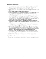
Страница 2: ...sitioning Your Playcenter 3 Tools Required for Assembly 3 Helpful Installation Hints 4 Suggested Playground Surfacing 5 Operating Instructions 6 Maintenance Instructions 7 Disposal Instructions 7 CPSC...
Страница 3: ...HELP WITH WHAT YOU NEED For more efficient service please log onto our website at www creativecedardesigns com and fill out a request for missing or damaged parts A completed product registration is...
Страница 4: ...n your installation continued satisfaction and safe operation of your Creative Cedar Designs purchase Always keep the safety of your children in mind as your play structure is being built and as your...
Страница 5: ...idea to place your Playcenter in an area that is convenient for adults to watch children at play 6 Create a site free of obstacles that could cause injuries such as low overhanging tree branches over...
Страница 6: ...you understand more clearly the installation process and help to eliminate unnecessary mistakes 7 Pay close attention to the diameter and length of each bolt and screw 8 Swing hangers should be burie...
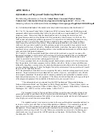
Страница 7: ...Standard Specification of Impact Attenuation of Surfacing Materials within the Use Zone of Playground Equipment The following chart explains the fall height in feet from which a life threatening head...
Страница 8: ...to sit in the center of the swings with their full weight on the seats 9 Instruct children not to use the equipment in a manner other than intended 10 Instruct children to always go down slides feet f...
Страница 9: ...parts 6 For rusted areas on metallic members such as monkey bars hand supports brackets etc sand and repaint using a non lead based paint meeting the requirements of Title 16 CRF Part 1303 7 Inspect w...
Страница 10: ...ecause children may deliberately jump from a moving swing the shock absorbing material should extend in the front and rear of a swing a minimum distance of 2 times the height of the pivot point measur...
Страница 11: ...may present a choking hazard to small children Please keep these bags and all plastic bags out of the reach of children Do no allow children to play with them and dispose of them immediately when emp...
Страница 12: ...h phase thoroughly The written steps may include important information not shown in the illustrations 4 Pay close attention to the Items needed and Hardware needed sections of each phase They can be a...
Страница 13: ...RIDGE H PF3819 1 1 X 5 X 25 BRIDGE I PF3818 1 1 X 5 X 24 1 2 BRIDGE J PF3817 1 1 X 5 X 24 BRIDGE K PF3816 6 1 X 3 5 8 X 24 STEPS PF3815 2 1 X 3 1 2 X 49 3 8 BASE LONG PF3808 2 1 X 3 1 2 X 27 STEP FRON...
Страница 14: ...Accessories 26 BRIDGE SPACERS P301 4 FENCE STAPLE H 8 CABLE CLAMP O2 1 BRIDGE CABLE O1 1 BRIDGE SUPPORT STRAP M301 2 ROPE RAILING Q 12 Parts Identification Wooden Bridge g 4 GREEN L BRACKET M002...
Страница 15: ...oc Nut 5 16LN 5 16 x 1 1 2 Lag Bolt L 8 1 Do not include bolt head when measuring length of bolt NOTES 2 Include full length of deck screw when measuring 1 4 1 1 2 3 4 2 3 4 5 6 It is very important t...
Страница 16: ...T 1 x 3 1 2 x 49 3 8 BASE LONG 1 x 3 5 8 x 24 STEPS 1 x 5 x 24 BRIDGE K 1 x 5 x 24 1 2 BRIDGE J 1 x 5 x 25 BRIDGE I 1 x 5 x 25 1 2 BRIDGE H 1 x 5 x 26 BRIDGE G 1 x 5 x 26 1 2 BRIDGE F 1 x 5 x 27 BRIDG...
Страница 17: ...hase 25 SLIDE ATTACHMENT 15 POSITION SLIDE CENTERED IN AN OPENING AND 4 INTO THE TOWER AS SHOWN INSTALL 4 TRUSS SCREWS PER SLIDE LARGE WAVE SLIDE GREEN Phase Parts Phase Hardware 1 Truss Head Screw S...
Страница 18: ...shown in STEP 1 2 Attach Step Support boards as shown in STEP 2 3 Attach Bridge Platform Step boards as shown in STEP 3 4 Attach Step Support boards as shown in STEP 4 PF3830 8 3 8 PF3805 PF3837 PF38...
Страница 19: ...pe Railing Support boards as shown in STEP 2 3 Attach Bridge Cable Support board as shown in STEP 3 4 Attach Bridge Platform Angle Support boards as shown in STEP 4 20 COUNTER BORE S FACING THIS SIDE...
Страница 20: ...BRIDGE ASSEMBLY STEP 2 STEP 1 63 1 2 GAP PF 3829 8 2 1 2 DECK SCREWS Rope Railing Support must be plumb and level Assemble Bridge Platform cont HOLE DETAIL 1 Attach Top Step boards as shown in STEP 1...
Страница 21: ...Z3259 BRIDGE SUPPORT WZ3259 BRIDGE SUPPORT LD203 UPRIGHT LD203 UPRIGHT LM226 WALL RAIL LM219 END FLOOR SUPPORT 2 3 1 2 LAG SCREWS BOTH SIDES 2 5 16 FLAT WASHERS STEP 1 1 MARK TWO HOLES ON UPRIGHTS AS...
Страница 22: ...p 2 Mark and drill 4 5 16 holes thru upgrights 2 on each upright Step 3 Insert 4 5 16 T nuts into backside of uprights Step 4 Attach M301 Support Strap with 4 1 1 4 deck screws 4 5 16 X 3 1 4 Hex bolt...
Страница 23: ...1 Phase 31 BRIDGE ASSEMBLY 5 16 x 6 DRILL BIT LD203 UPRIGHT 65 1 16 80 1 16 Bridge Tower Prep Rope Railing Step 1 Mark hole locations centered on uprights as shown Step 2 Drill 5 16 holes at locations...
Страница 24: ...Eye bolt thru platform upright and secure with hardware as shown 3 Repeat steps for opposite side NOTE Space between upright and first rope Phase Hardware Phase Hardware K1 8 5 16 Flat Washer G1 8 5...
Страница 25: ...ope Railing as shown below The cable will be routed starting from the left Tower side through the Bridge Boards Platform sturcture then back through the Bridge Boards as indicated by the arrows 1 1 X...
Страница 26: ...le through left side of Bridge Boards as described in previous page Step 2 Thread cable through Platform down through the top across to the opposite side Step 3 Route cable through right side of Bridg...
Страница 27: ...IDGE CLEAT PF3783 H 2 Fence Staple STEP 1 STEP 2 2 1 4 4 1 4 Assemble Bridge Secure Cable and Attach Cleats 1 Secure cable running underneath the Bridge Platform as shown in STEP 1 2 Attach Cleats as...
Страница 28: ...rs STEP 1 Assemble Bridge Secure Cable and Attach tower 1 Thread Bridge Cable thru M301 Bracket WZ3259 Support as shown in STEP1 NOTE Deck boards are removed for clarity Bridge Spacers LD203 Bridge Ca...
Страница 29: ...t and install Cable Clamp tight to WZ3259 Support 2 Install a fence staple above the Cable Clamp into WZ3259 Support for each cable as shown in STEP 1 3 Drill 3 8 hole s at location shown on uprights...
Страница 30: ...CAP 5 16 LOCK NUT 5 16 FLAT WASHER EYE BOLT ASSEMBLY UNDER DECK VIEW LD203 TOP VIEW LM211 LM210 WZ3259 BRIDGE SUPPORT LM219 Assemble Bridge Finish and Secure Bridge 1 Thread cable through Eye Bolt and...
Страница 31: ...ry board is secure Make sure playset is level SECURE PLAYSET 1 Place anchors at the locations shown 2 Twist the anchors into the ground until only the loop is exposed as shown 3 Place the metal strap...
Страница 32: ...damaged by acts of God negligence misuse or accident or which have been modified or repaired by unauthorized persons b the cost of labor c the cost of shipping the product any part or any replacement...
Страница 33: ...scription of the warranty issue 3 Photos of warranted parts and of the entire play system If any of the above steps are not completed there may be delays in the completion of your claim or possibly wa...
Страница 34: ..._______________ City State Zip Code ___________________________________________________ Phone ________________________________________________________________ Date of Purchase ________________________...
Страница 35: ...stration Card along with a copy of the receipt and return to Creative Cedar Designs within 30 days of original purchase in order to validate time of purchase for warranty FOLD HERE Place Stamp Here Cr...