7
4. DISASSEMBLY
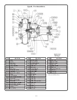
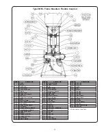
The disassembly instructions apply to the series of pumps
in general and may vary slightly on special units. If complete
disassembly is not necessary, use only those steps which
apply. Close gate valve in discharge and suction piping.
Inspect all parts removed to determine whether suitable for
reuse. It is recommended that all packing, gaskets and
O-rings be replaced with new ones during reassembly.
NOTE: Special precautions must be observed when
handling mechanical seals, so as not to damage the
lapped faces of the seals.
Unless casing (1) or suction cover (9) is damaged, or it is
necessary to replace suction cover wear ring (25), it may
not be necessary to remove the suction and discharge
piping to service the power end.
a. Remove drain plug (216) from casing or (231)
from suction elbow.
b. Remove all cooling or lubrication lines.
c. Disconnect power supply to motor and remove
motor; coupling spacer or
fl
exible drive shaft, so
that power frame assembly may be removed
from the casing (1).
d. Remove casing cap screws (212) and packing
box cover cap screws (334), where used and
separate power end from casing (1).
e. Remove impeller screw (26) by turning counter
clockwise, washer (210), impeller screw gasket
(28) and pull impeller (2) from the shaft with an
impeller or wheel puller. Remove impeller key
from the shaft, also shaft sleeve gasket (38).
PACKING BOX COVER (11)
a. With Packing (13): Remove gland nuts (210),
or cap screws (282), gland clips (206) and gland
(11). Packing box cover may be removed from
frame (19). Remove packing (13) and lantern
ring (29) from packing box cover and clean the
bore of the cover.
b. With Mechanical Seal (89): Remove gland nuts
(210) and carefully remove packing box cover
from frame (19). Inboard stationary seal seat
can be pushed from the cover and outboard
stationary seal seat can be removed from seal
gland. Before removing seal rotating assembly,
depending on type of seal furnished, scribe a
mark on sleeve to show location of spring
retainer, then seal rotating assembly may be
removed, being careful so as no to damage
sealing faces, O-ring, etc.
SHAFT SLEEVE (14)
The shaft sleeve is mounted on the pump shaft (6) by
means of heat shrink
fi
t. To remove shaft sleeve, dismantle
power frame as below, place shaft in a vise and proceed as
follows:
1. With a hand grinder and a thin grinding wheel
(approx. 1/8” wide), cut a groove axially along the
sleeve to the shoulder of the shaft. Grind the
groove as deep as possible without damaging
the
shaft.
2. After the groove has been cut, insert a wedge
tipped cold chisel into the groove at the impeller
end of the sleeve. Support shaft on a V block
under the sleeve. Tap chisel sharply with a hammer
until crack occurs along the base of the groove.
3. Pry groove apart and remove sleeve from shaft.
FRAME (19)
a. Remove pump half of
fl
exible coupling and key
(46) from pump shaft (6). Remove cap screws
(213), cap screws (332) and jack screws (286)
with adjusting lock nut (204) and pull bearing
cover (37) and seal (49) from bearing housing (33).
b. Open tangs of lockwasher (69) and unscrew and
remove bearing locknut (22) and bearing
lockwasher
(69).
c. Insert a small pry bar at several points under the
fl
ange of the bearing housing (33) and carefully
force the shaft (6) with bearing housing (33)
bearings (18 and 16) and grease retainer (51)
from the coupling end of the frame (19).
d. Mark position of grease retainer on the shaft,
then remove grease retainer and bearing (16)
from impeller end of shaft.
NOTE:
To remove inner race roller bearing (16), carefully
apply heat to the inner race until it can be pulled from
shaft.
e. With bearing puller, remove bearing housing (33)
and bearing (18) from coupling end of shaft.
Press bearing from the bearing housing.
f. Wash bearings, bearing housing and bearing
covers to remove old grease, also
fl
ush old
grease from frame (19). Press seals (41 and 49)
from bearing covers (35 and 31) ad inspect for
wear.
WEARING RINGS (8 and 25)
a. To replace suction cover ring (25), remove cap
screw (215) and suction cover (9) from casing (1).
Remove machine screws (343) and then remove
ring (25). Clean ring seat before installing new ring.
b. To replace impeller ring (8), (remove set screws
(296) when used), place a wedge-tipped or
pointed cold chisel against the side of the ring
and tap chisel sharply with a hammer, forcing the
ring from the impeller (2).
5. REASSEMBLY
FRAME (19)
a. Position grease retainer (51) onto the shaft (6) to
position previously-marked and tighten set
screws. Press inboard ball bearing (16) onto the
shaft until inner race is against shaft shoulder.
Apply fresh grease to the bearing (don’t over
grease),
fi
ll chamber 1/3 full.
b. Carefully press outboard ball bearing (19) into the
bearing housing (33) until seated in the bottom
of the housing. Press bearing housing assembly
onto the shaft (6) until bearing inner race is
against shaft shoulder. Apply fresh grease to the
being and the housing.
Содержание Weinman B Series
Страница 16: ...Notes ...


