9
Position unit upright, using blocks to avoid resting unit on
shaft. Remove gland nut (12b), friction rings (12c) and
grommet (12d) from motor housing (11), see Figure 8.
Remove socket head cap screws (36) and lift motor housing
(11) from lower end bell (10). Slide motor housing (11) up
cable (12), until wire connectors and ground screw are
exposed. Remove cable lead wires from motor lead wires
by disconnecting wire connectors (19) and ground screw
(20) from motor (14). The wiring connections should be
noted to insure correct connections when reassembling.
Motor -
Remove the motor bolts and lift motor stator from
motor rotor and lower end bell (10). Unscrew conduit
bushing (16) from lower end bell (10) and lift motor rotor,
shaft, bearing (21), rotating portion of seal (1), washers (25)
& (33), and conduit bushing (16) from lower end bell (10).
Inspect windings for shorts and check resistance values.
Check rotor for wear, if rotor or the stator windings are
defective, the complete motor must be replaced.
To test the temperature sensor (if equipped), check the
continuity between the black and white wires. If found to be
defective contact a motor service station or Barnes Service
Department. Check motor capacitor (18) on single phase
units with an Ohm meter by fi rst grounding the capacitor
by placing a screwdriver across both terminals and then
removing screwdriver. Connect Ohm meter (set on high
scale) to terminals, if needle moves to infi nity ( ∞ ) then
drifts back, the capacitor is good. If needle does not move
or moves to infi nity (∞) and does not drift back, replace
capacitor (18).
Seal -
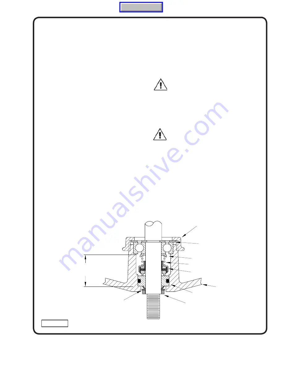
Remove rotating member (1a), spring (1c) and
retaining ring (1d) from shaft. (see Figure 5). Examine all seal
parts and especially contact faces. Inspect seal for signs of
wear such as uneven wear pattern on stationary members,
chips and scratches on either seal face.
DO NOT
interchange
seal components, replace the entire shaft seal (1).
If replacing seal, remove stationary (1a) from lower end bell
(10) by prying out with fl at screwdriver.
CAUTION ! - Handle seal parts with extreme
care. DO NOT scratch or mar lapped surfaces.
Bearing -
Examine bearing (21) and replace if required. If
replacement is required, remove bearing (21) from motor
shaft using a wheel puller. Washers (25), (33) and conduit
bushing (16) can now be removed from motor shaft.
IMPORTANT ! - All parts must be clean before
reassembly.
F-3.2) Reassembly:
Bearing -
When replacing bearing, be careful not to damage
the rotor or shaft threads. Clean the shaft thoroughly. Slide
conduit bushing (16) and washers (25), (33) over motor shaft.
Apply adhesive compound to the shaft and press bearing
(21) on the motor shaft, position squarely onto shaft applying
force to the inner race of the bearing only, until bearing seats
against shoulder of the shaft.
SEAL ASSEMBLY (1)
RETAINING RING (1D)
LOWER END BELL (10)
SPRING (1C)
ROTATING MEMBER (1B)
STATIONARY (1A)
CONDUIT BUSHING (16)
WASHER (25) & (33)
SPACER (32) and
SHIMS (39) & (40)
EXCLUSION SEAL (31)
MOTOR END
(INBOARD END)
PUMP END
(OUTBOARD END)
FIGURE 5
Manual Index
Содержание Barnes SE51 Series
Страница 13: ...13 FIGURE 10 Manual Index ...
Страница 14: ...14 FIGURE 11 Manual Index ...


