Crane BARNES 4SE Series Скачать руководство пользователя страница 8

SECTION E: PREVENTATIVE MAINTENANCE

As the motor is oil filled, no lubrication or other maintenance is
required, and generally Barnes Pumps will give very reliable
service and can be expected to operate for years on normal
sewage pumping without failing. However as with any
mechanical piece of equipment a preventive maintenance
program is recommended and suggested to include the
following checks:

1) Inspect motor chamber for oil level and contamination 

and repair as required per section F-1.

2) Inspect impeller and body for excessive build-up or

clogging and repair as required per section F-2.

3) Inspect motor, bearings and shaft seal for wear or

leakage, replace as required per section F-3.

SECTION F: SERVICE AND REPAIR

NOTE:

 All item numbers in ( ) refer to Figures 8 & 9.

WARNING ! 

ELECTRICAL POWER TO THE PUMP MOTORS MUST

BE DISCONNECTED AND LOCKED OUT TO PREVENT

ANY DANGEROUS ELECTRICAL HAZARDS OR

PERSONNEL DANGER BEFORE ANY SERVICE WORK

IS DONE TO THE PUMP.

CAUTION ! 

OPERATING PUMP BUILDS UP HEAT AND

PRESSURE; ALLOW TIME FOR PUMP TO COOL TO

ROOM TEMPERATURE BEFORE HANDLING OR

SERVICING.

F-1) Lubrication:

Anytime the pump is removed from operation the cooling oil in
the motor housing (3), must be checked visually for oil level
and contamination.

F-1.1) Checking Oil:
Motor Housing-

 To check oil, set unit upright. Remove Pipe

Plug (2) or (36) from motor housing (3) With a flashlight,
visually inspect the oil in the motor housing (3) to make sure it
is clean, clear and that oil level is above all internal
componentry.

F-1.2) Testing Oil:
1.

Place pump on it’s side, remove Pipe Plug (2) or (36) from
motor housing (3) and drain oil into a clean, dry container.

2.

Check oil for contamination using an oil tester with a range
to 30 Kilovolts breakdown.

3.

If oil is found to be clean and uncontaminated (measure
above 15 KV. breakdown), refill the motor housing as


per section F-1.3.

4.

If oil is found to be dirty or contaminated (or measures
below 15 KV. breakdown), the the pump must be carefully
inspected for leaks at the shaft seal (9), Gland nut (28b) 
and (39b if equipped), O-ring (24), Gasket (13), pipe plugs
(2) or (36) before refilling with oil. To locate the leak, 
perform a pressure test as per section F-1.4. After leak is
repaired, refill with new oil as per section F-1.3.

F-1.3) Replacing Oil:
Motor Housing-

 Drain all oil from motor housing and dispose

of properly. Refill with (see parts list for amount) new cooling
oil as per Table 1. An air space must remain in the top of the
motor housing to compensate for oil expansion (see Fig. 8).
Set unit upright and fill only until the motor, as viewed through
the pipe plug opening, is just covered and no more. Apply pipe
sealant to pipe plug (2) or (36) and install in motor housing (3).

WARNING ! 

DO NOT OVERFILL OIL 

OVERFILLING OF MOTOR HOUSING WITH OIL CAN

CREATE EXCESSIVE AND DANGEROUS HYDRAULIC

PRESSURE WHICH CAN DESTROY THE PUMP AND

CREATE A HAZARD. OVERFILLING OIL VOIDS

WARRANTY.

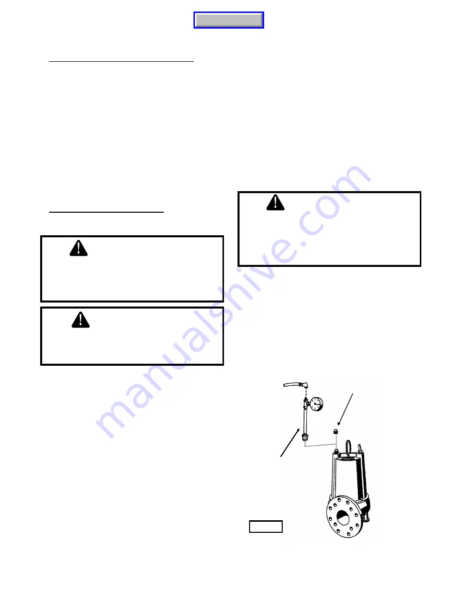
F-1.4) Pressure Test:
Motor Housing- 

Before checking the pump for leaks around

the shaft seal, square rings, and cord inlet, the oil level should
be full as described in section F-1.3. Remove pipe plug (2) or
(36) from motor housing (3). Apply pipe sealant to pressure
gauge assembly and tighten into pipe plug hole (see Fig. 2).
Pressurize motor housing to 10 P.S.I. Use a soap solution
around the sealed areas and inspect joints for "air bubbles". If,
after five minutes, the pressure is still holding constant, and no
"bubbles" are observed, slowly bleed the pressure and remove
the gauge assembly. Replace the pipe plug using a sealant. If
the pressure does not hold, then the leak must be located.

10 PSI AIR

 ⇒

Remove Pipe Plug

PRESSURE GAUGE
ASSEMBLY 
(See Parts List)

Fig. 2

8

Manual Index

Содержание BARNES 4SE Series

Страница 1: ...ges may occur As such Crane Pumps Systems Inc reserves the right to change product without prior written notification SERIES 4SE 0 9 1 4 and 1 9 HP 1750 RPM BARNES 420 Third Street P O Box 603 83 West Drive Brampton Piqua Ohio 45356 0603 Ontario Canada L6T 2J6 Phone 937 778 8947 Phone 905 457 6223 Fax 937 773 7157 Fax 905 457 2650 www cranepumps com PUMPS SYSTEMS A Crane Co Company Manual Index SU...

Страница 2: ...ODED VIEW Fig 9 16 PARTS LIST 17 18 WARRANTY INFORMATION 19 WARRANTY START UP REPORT WARRANTY REGISTRATION SPECIAL TOOLS AND EQUIPMENT INSULATION TESTER MEGGER DIELECTRIC TESTER SEAL TOOL KIT see parts list PRESSURE GAUGE KIT see parts list Other brand and product names are trademarks or registered trademarks of their respective holders Barnes is a registered trademark of Barnes Pumps Inc Barnes P...

Страница 3: ...any pump and on end suction and self priming pump the heat build may cause the generation of steam with resulting dangerous pressures It is recommended that a high case temperature switch or pressure relief valve be installed on the pump body ELECTRICAL 21 To reduce risk of electrical shock pump must be properly grounded in accordance with the National Electric Code NEC or Canadian Electrical Code...

Страница 4: ...N Hardware 300 Series Stainless CABLE ENTRY 15ft 4 5M Cord Plug On 115 Volt Pressure Grommet For Sealing And Strain Relief SPEED 1750 RPM Nominal UPPER BEARING Design Sleeve Lubrication Oil Load Radial LOWER BEARING Design Single Row Ball Lubrication Oil Load Radial Thrust MOTOR Design NEMA L Single Phase NEMA B Three Phase Torque Curve Completely Oil Filled Squirrel Cage Induction Insulation Clas...

Страница 5: ...nd tested before the long term storage begins such installation will be allowed provided 1 The pump is not installed under water for more than one 1 month 2 Immediately upon satisfactory completion of the test the pump is removed thoroughly dried repacked in the original shipping container and placed in a temperature controlled storage area B 4 Service Centers For the location of the nearest Barne...

Страница 6: ...control panel must be made in accordance with all applicable electric codes It is recommended that a junction box if used be mounted outside the sump or be of at least Nema 4 EEMAC 4 construction if located within the wet well Do not use the control cable to lift pump NOTE THE WHITE WIRE IS NOT A NEUTRAL OR GROUND LEAD BUT A POWER CARRYING CONDUCTOR C 4 3 Overload Protection C 4 3 1 Three Phase Op...

Страница 7: ...Test Before the pump is put into service an insulation megger test should be performed on the motor The resistance values ohms as well as the voltage volts and current amps should be recorded on the start up report D 3 3 Pump Down Test After the pump has been properly wired and lowered into the basin sump or lift station it is advisable to check the system by filling with liquid and allowing the p...

Страница 8: ...down 3 If oil is found to be clean and uncontaminated measure above 15 KV breakdown refill the motor housing as per section F 1 3 4 If oil is found to be dirty or contaminated or measures below 15 KV breakdown the the pump must be carefully inspected for leaks at the shaft seal 9 Gland nut 28b and 39b if equipped O ring 24 Gasket 13 pipe plugs 2 or 36 before refilling with oil To locate the leak p...

Страница 9: ...te impeller to check for binding Position gasket 13 on volute flange and position impeller and motor housing assembly on volute 10 Apply thread locking compound to cap screw 11 and position lockwasher 12 on cap screw 11 and screw into volute 10 Torque to 8 ft lbs Check for free rotation of motor and impeller F 3 Motor Bearing and Seal Service F 3 1 Disassembly and Inspection To examine or replace ...

Страница 10: ...otor shaft position squarely onto shaft applying force to the inner race of the bearing only until bearing seats against shoulder of the shaft Seal Clean and oil seal cavity in lower end bell 22 Press stationary member 9a firmly into lower end bell 22 using a seal pusher see parts list seal tool kit nothing but the seal pusher is to come in contact with seal face see Figure 4 Make sure the station...

Страница 11: ...le optional Insert one friction ring 39c grommet 39d and another friction ring 39c into motor housing 3 Apply pipe sealant to gland nut 39b and screw into motor housing 3 Torque gland nut 39b to 15 ft lbs to prevent water leakage see Figure 6 F 3 4 Wiring Connections Check power cable 28 and control cable 39 if used for cracks or damage and replace if required see Figure 6 Place parts 28b c d on p...

Страница 12: ...Red 2 White 3 4 7 Together 5 8 Together 6 9 Together TEMPERATURE SENSOR Optional Control Cable 39a Lead Number Black P1 Temperature Sensor White P2 Temperature Sensor Fig 7 G L1 L2 L3 G T1 T7 T2 T8 T3 T9 T4 T5 T6 MOTOR LEADS POWER Large Cable G R E E N B L A C K R E D W H I T E MOTOR LEADS G L1 L2 G T1 T2 G R E E N B L A C K W H I T E POWER Large Cable Temperature Sensor Leads CONTROL Small Cable ...

Страница 13: ...mpeller cavity and inlet of any obstruction 9 Loosen union slightlyto allow trapped air to escape Verify that turn off level of switch is set so that impeller cavity is always flooded Clean vent hole 10 Check rotation If power supply is three phase reverse any two of three power supply leads to ensure proper impeller rotation 11 Repair fixtures as required to eliminate leakage 12 Check pump temper...

Страница 14: ...n This number is used for ordering and obtaining information G 3 MODEL NUMBER This designation consists of numbers and letters which represent the discharge size series horsepower motor phase and voltage speed and pump design This number is used for ordering and obtaining information G 4 SERIAL NUMBER The serial number block will consist of a six digit number which is specific to each pump and may...

Страница 15: ...Fig 8 15 Manual Index ...

Страница 16: ...Fig 9 16 Manual Index ...

Страница 17: ...en Buna N 023701SB Silicon Silicon Buna N 023701SD Carbon Ceramic Viton 023701SF Tungsten Tungsten Viton 023701SH Silicon Silicon Viton 023701SK Silicon Tungsten Buna N 023701SM Carbon Ni Resist Buna N 023701SN Carbon Ni Resist Neoprene 023701SP 10 1 Volute 066742 11 4 Cap Screw Hex Hd 5 16 18 x 1 25 Lg Stainless 1 131 1 12 4 Lockwasher 5 16 Stainless 026322 13 1 Gasket 027344 14 3 Nipple 005808 1...

Страница 18: ...9318 39 1 Cord Set Assembly Optional Temp Sensor See Table 2 39a 1 Cord Set Not Sold Separately 39b 1 Gland Nut 051448 39c 2 Friction Ring 051449 39d 1 Grommet 051451 40 1 Warning Lable 088350 TABLE 2 POWER CABLE SETS MODELS LENGTH ITEM 28 1 PHASE 115V CSA LISTED ITEM 28 1 PHASE 230V CSA LISTED ITEM 28 3 PHASE Non CSA Units ITEM 28 OPTIONAL CSA LISTED 3 PHASE ITEM 39 OPTIONAL TEMP SENSOR CSA 3 PHA...

Страница 19: ... warranty contact your local Crane Pumps Systems Inc Distributor RETURNED GOODS RETURN OF MERCHANDISE REQUIRES A RETURNED GOODS AUTHORIZATION CONTACT YOUR LOCAL CRANE PUMPS SYSTEMS INC DISTRIBUTOR Products Returned Must Be Cleaned Sanitized Or Decontaminated As Necessary Prior To Shipment To Insure That Employees Will Not Be Exposed To Health Hazards In Handling Said Material All Applicable Laws A...

Страница 20: ...rformance Any additional guarantees in the nature of performance specifications must be in writing and such writing must be signed by our authorized representative Due to inaccuracies in field testing if a conflict arises between the results of field testing conducted by or for user and laboratory tests corrected for field performance the latter shall control Components or accessories supplied by ...

Страница 21: ...Does Impeller Turn Freely By Hand YES NO Condition Of Equipment GOOD FAIR POOR Condition Of Cable Jacket GOOD FAIR POOR Resistance of Cable Jacket GOOD FAIR POOR Resistance of Cable and Pump Motor measured at pump control Red Black Ohms Red White Ohms White Black Ohms Resistance Of Ground Circuit Between Control Panel and Outside of Pump Ohms MEG Ohms Check of Insulation Red to Ground White to Gro...

Страница 22: ...Off L1 L2 L2 L3 L3 L1 Voltage supply at panel line connection Pump On L1 L2 L2 L3 L3 L1 Amperage Load connection Pump On L1 L2 L3 FINAL CHECK Is pump seated on discharge properly Check for leaks Does check valves operate properly Flow Does station appear to operate at proper rate Pump down time Noise Level High Medium Low Comments Equipment Difficulties during start up MANUALS Has operator receive...

Страница 23: ...NO PART NO BRAND FOLD HERE IMPORTANT WARRANTY REGISTRATION Your product is covered by the enclosed Warranty Complete the Warranty Registration Form and returned to Crane Pumps Systems Inc Warranty Service Group IMPORTANT If you have a claim under the provision of the warranty contact your local Crane Pumps Systems Inc Distributor Manual Index ...

Страница 24: ...CRANE PUMPS SYSTEMS INC WARRANTY SERVICE GROUP 420 THIRD STREET P O BOX 603 PIQUA OHIO 45356 0603 U S A PLACE STAMP HERE FOLD HERE AND TAPE DO NOT STAPLE Manual Index ...

Отзывы: