


7
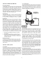
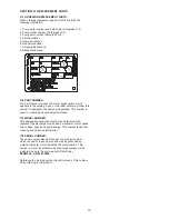
C-4) Electrical Connections:
An acceptable motor control switch shall be provided at the
time of installation.
C-4.1) Power and Control Cords:
The cord assembly mounted to the pump must not be
modifi ed
in any way except for shortening to a specifi c application.
Any splice between the pump and the control panel must
be made in accordance with all applicord electric codes. It is
recommended that a junction box, if used, be mounted outside
the sump or be of at least Nema 4 (EEMAC-4) construction if
located within the wet well.
DO NOT USE THE POWER OR
CONTROL CORD TO LIFT PUMP.
NOTE:
THE WHITE WIRE
IS NOT A NEUTRAL OR GROUND LEAD, BUT A POWER
CARRYING CONDUCTOR.
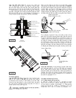
C-4.2) Overload Protection:
C-4.2-1) Three Phase (Optional) -
The normally closed (N/C)
thermal sensor is embedded in the motor windings and will
detect excessive heat in the event an overload condition
occurs. The thermal sensor will trip when the windings become
too hot and will automatically reset itself when the pump motor
cools to a safe temperature. It is recommended that the
thermal sensor be connected in series to an alarm device to
alert the operator of an overload condition, and/or the motor
starter coil to stop the pump. In the event of an overload, the
source of this condition should be determined and rectifi ed
immediately.
DO NOT LET THE PUMP CYCLE OR RUN IF
AN OVERLOAD CONDITION OCCURS !
C-4.2-2) Single Phase (Standard) -
The type of in-winding
overload protector used is referred to as an inherent
overheating protector and operates on the combined effect
of temperature and current. This means that the overload
protector will trip out and shut the pump off if the windings
become too hot, or the load current passing through them
becomes too high. It will then automatically reset and start the
pump up after the motor cools to a safe temperature.
In the event of an overload, the source of this condition should
be determined and rectifi ed immediately.
DO NOT LET THE
PUMP CYCLE OR RUN IF AN OVERLOAD CONDITION
OCCURS !
If current through the temperature sensor exceeds the values
listed, an intermediate control circuit relay must be used
to reduce the current or the sensor will not work properly.
TEMPERATURE SENSOR ELECTRICAL RATINGS
Volts
Continuous
Amperes
Inrush
Amperes
220-240
1.50
15.0
440-480
0.75
7.5
600
0.60
6.0
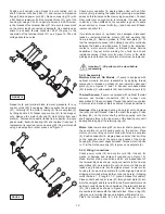
C-4.3) Moisture Sensors- DS Models: (Optional)
A normally open (N/O) detector is installed in the pump
seal chamber which will detect any moisture present. It is
recommended that this detector be connected in series to an
alarm device or the motor started coil to alert the operator that
a moisture detect has occurred.
In the event of a moisture detect, check the individual moisture
sensor probe leads for continuity
, (∞ resistance = no moisture)
and the junction box/control box for moisture content. The
above situations may induce a false signal in the moisture
detecting circuit. If none of the above tests prove conclusive,
the pump(s) should be pulled and the source of the failure
identifi ed and repaired.
IF A MOISTURE DETECT HAS
OCCURRED SCHEDULE MAINTENANCE AS SOON AS
POSSIBLE.
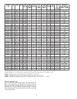
C-4.4) Wire Size:
Consult a qualifi ed electrician for proper wire size if additional
power cord length is required. See table on page 8 for
electrical information.
SECTION: D START-UP OPERATION
D-1) Check Voltage and Phase:
Before operating pump, compare the voltage and phase
information stamped on the pump identifi cation plate to the
available power.
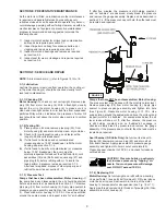
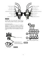
D-2) Check Pump Rotation:
Before putting pump into service for the fi rst time, the motor
rotation must be checked. Improper motor rotation can
result in poor pump performance and can damage the motor
and/or pump. To check the rotation, suspend the pump
freely, momentarily apply power and observe the “kickback”.
“Kickback” should always be in a counter-clockwise direction
as viewed from the top of the pump motor housing.
D-2.1) Incorrect Rotation for Three-Phase Pumps:
In the event that the rotation is incorrect for a three-phase
installation, interchange any two power cord leads at the
control box.
DO NOT
change leads in the cord housing in the
motor. Recheck the “kickback” rotation again by momentarily
applying power.
D-2.2) Incorrect Rotation for Single-Phase Pumps:
In the unlikely event that the rotation is incorrect for a single
phase pump, contact a Barnes Pumps Service Center.
D-3) Start-Up Report:
Included at the end of this manual is a start-up report form,
this form is to be completed as applicord. Return one copy to
Barnes Pumps, Inc. and store a copy in the control panel or
with the pump manual if no control panel is used. It is important
to record this data at initial start-up since it will be useful to
refer to should servicing the pump be required in the future.
D-3.1) Identifi cation Plate:
Record the numbers from the pump identifi cation plate on
both START-UP REPORT provided at the end of the manual
for future reference.
D-3.2) Insulation Test:
Before the pump is put into service, an insulation (megger)
test should be performed on the motor. The resistance values
(ohms) as well as the voltage (volts) and current (amps)
should be recorded on the start-up report.
Содержание 104189
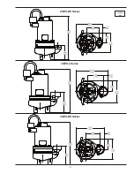
Страница 5: ...5 inches mm 2SEV DS Series 3SEV L Series 3SEV DS Series ...
Страница 14: ...14 FIGURE 14 CONTIUED ...
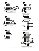
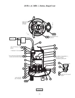
Страница 17: ...17 FIGURE 15 2SEV L 3SEV L Series Single Seal ...
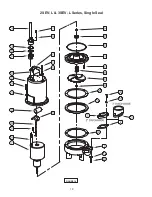
Страница 18: ...18 FIGURE 16 2SEV L 3SEV L Series Single Seal ...
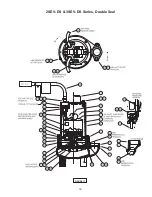
Страница 19: ...19 FIGURE 17 2SEV DS 3SEV DS Series Double Seal ...
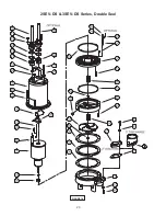
Страница 20: ...20 FIGURE 18 2SEV DS 3SEV DS Series Double Seal ...


