
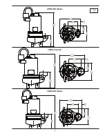


13
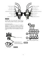
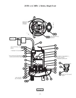
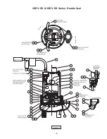
FIGURE 13
completely below the snap ring groove. Place snap ring
(19) into groove in cord entry bore of housing. Repeat
terminal block installation for control cord, if equipped.
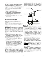
F-4.4) Cord Assemblies:
Power/Control Cord
- Refi ll the cooling oil as outlined in
paragraph F-1.3. Make wire connections as outlined in
paragraph F-4.3. Insert female end of cord plug into housing
bore aligning timing mark with hole in terminal block (21), see
Figure 13. Compress cord plug with compression
fl ange (16a)
by tightening hex bolts (11) into the housing (6). Torque to 132
in-lbs.
FIGURE 12
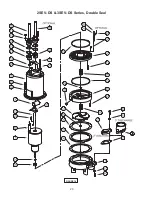
FIGURE 14
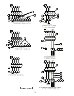
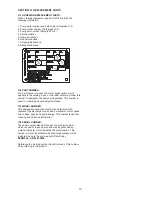
SINGLE PHASE - 240 VOLT AC (PSC)
Содержание 104189
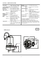
Страница 5: ...5 inches mm 2SEV DS Series 3SEV L Series 3SEV DS Series ...
Страница 14: ...14 FIGURE 14 CONTIUED ...
Страница 17: ...17 FIGURE 15 2SEV L 3SEV L Series Single Seal ...
Страница 18: ...18 FIGURE 16 2SEV L 3SEV L Series Single Seal ...
Страница 19: ...19 FIGURE 17 2SEV DS 3SEV DS Series Double Seal ...
Страница 20: ...20 FIGURE 18 2SEV DS 3SEV DS Series Double Seal ...


