


8
F-2) Impeller and Volute Service:
F-2.1) Disassembly and Inspection:
To clean out volute (26) or replace impeller (28), or replace
wear ring (31), disconnect power, remove hex nuts (20) and
vertically lift motor and seal assembly from body (26). Clean
out body if necessary. Clean and examine impeller (28), for
pitting or wear and replace if required, inspect gasket (41)
and replace if cut or damaged. If the impeller (28) requires
replacing, remove cap screw (34) and washer (35). The
impeller is keyed onto the shaft with a square key (33) and
to remove, pull impeller straight off the shaft using a wheel
puller, if required. If the wear ring (31) requires replacing, split
the wear ring (31) and remove, be careful not to damage the
volute. Before reinstalling, check the motor shaft and impeller
bore for damage.
F-2.2) Reassembly:
To install wear ring (31) fi rst apply retaining compound to the
bore of body (26) and then press wear ring (31) into bore of
body (26) until seated. To install impeller (28), apply a thin
fi lm of oil to motor shaft and slide impeller straight onto shaft,
keeping keyways lined up. Drive key (33) into keyway. Locate
washer (35), apply thread locking compound to cap screw (34)
threads, thread cap screw (34) into shaft and torque to 35 ft.
lbs. Rotate impeller to check for binding. Position gasket (41)
on volute fl ange and install impeller and motor housing over
studs and onto volute (26). Apply thread locking compound
to threads of each stud (24). Thread nut (20) onto stud (24)
and torque to 24 ft. lbs. Check for free rotation of motor and
impeller.
F-3) Motor and Bearing Service
F-3.1) Disassembly and Inspection:
To examine or replace the motor (1) and bearings (3) and
(47), disassemble pump, volute and impeller (as outlined in
paragraph F-2.1) and disassemble seal plate and shaft seal
(as outlined in paragraph F-4.1). Drain oil from motor as
outlined in paragraph F-1.3.
Position unit upright, using blocks to avoid resting unit on shaft.
After removal of cable and box assembly (10) from motor
housing (2), remove cable lead wires from motor lead wires
and moisture and temperature sensors wires from control
cable by unscrewing connectors (12) and (17). The wiring
connections should be noted to insure correct connections
when reassembling. Remove cap screws (19) and hex nuts
(20).
Vertically lift the outside motor housing (2) from bearing bracket
(21) with lifting strap (7). Inspect square ring (42) for damage
or cuts. Remove the upper motor bolts and lift upper end
bell from motor (1). Examine upper bearing (3) and replace if
required. If replacement is required, remove bearing (3) from
motor shaft using a wheel puller. Remove the nuts (38) and
lockwashers (36) from lower motor studs (37).
Vertically lift stator. Inspect winding for shorts and resistance.
To test the temperature sensor, check for continuity between
the black and white wires. If found to be defective contact a
motor service station or Prosser Pumps service department.
Pull motor rotor and lower bearing (47) vertically from bearing
bracket (21). Examine bearing (47) and replace if required. If
replacement is required, remove bearing (47) from motor shaft
using a wheel puller. Check rotor for wear. If rotor or the stator
windings are defective, the complete motor must be replaced.
While disassembled, check moisture sensor wires (16), that
they are secured to electrodes (18) with lockwashers (15) and
screws (14).
IMPORTANT ! - All parts must be clean before
reassembly.
F-3.2) Reassembly:
Bearings -
When replacing bearings, be careful not to
damage the rotor or shaft threads. (If so equipped, Fill Notch
should face the rotor core for both upper and lower bearings.)
Clean the shaft thoroughly. Apply adhesive compound to
the shaft and press bearing (47) on the motor shaft, position
squarely onto the shaft applying force to the inner race of the
bearing only, until bearing seats against shoulder of the shaft.
Reassemble top bearing (3) in the same manner.
Motor -
Slide lower bearing (47) and motor rotor squarely into
the bearing bracket (21) until bearing seats on the bottom.
Position motor housing and stator into pilot, aligning studs
(37) with holes in bearing bracket (21). Apply thread locking
compound on studs (37) and position washers (36) and nuts
(38) on studs (37) and tighten. Torque nuts (38) to 18 ft. lbs.
Position upper motor end bell aligning holes and thread cap
screws into motor. Torque to 16 ft. lbs. Place all motor leads
above the motor. Position square ring (42) over bearing
bracket (21) and lower housing (2) over motor and into pilot.
Apply thread locking compound to cap screws (19) threads
and install with nut (20). Torque to 24 ft. lbs.
F-3.3) Wiring Connections:
Check power cable (10A) and control cable (10D), on conduit
box (10), for cracks or damage and replace complete conduit
box assembly (10), (see Fig. 4). Bring motor wires through wire
opening in top of housing (2),check sleeving (53) and replace
if required, position square ring (11) in conduit housing (10)
and reconnect motor leads to power cable and moisture and
temperature sensor leads to control cable using connectors
(12), (17) and insulators (54) as show in Fig. 3.
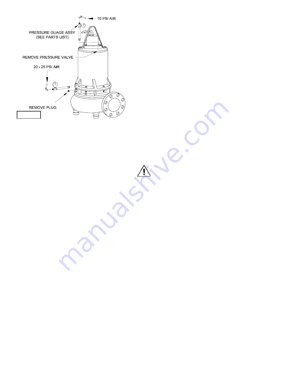
FIGURE 2
Содержание 6SED-L Series
Страница 13: ...13 FIGURE 9 ...
Страница 14: ...14 FIGURE 10 ...


