background image

Содержание EZ3 917.271090

Страница 1: ...sion engine which operates differently from built Before start the enginei read previously engines you and understand this Owner s Manual CAUTION Read and follow all Safety Rules and Instructions before operating this equip ment For answers to your questions about this product Call 1 800 659 5917 Sears Craftsman Help Line 5 am 5 pro Mon Sat Sears Roebuck and Co Hoffman Estates IL 60179 ...

Страница 2: ...ty service on your Craftsman riding equipment is available at no charge for 30 days from the date of purchase Please contact your nearest service center After 30 days from the date of purchase warranty service is available by taking your Craftsman riding equip ment to your nearest Sears Service Center Imhome warranty service will still be avail able after 30 days from the date of purchase but a st...

Страница 3: ...ud denly turn over if a wheel is over the edge of a cliff or ditch or if an edge caves in Do not mow on wet grass Reduced traction could cause sliding Do nottry to stabilize the machine by putting your foot on the ground Do not use grass catcher on steep slopes CHILDREN Tragic accidents can occur if the operator is not alert to the presence of children Children are often attracted to the machine a...

Страница 4: ...ful care of another responsible adult Be alert and turn machine off if children enter the area Before and when backing look behind and down for small children Mow up and clown slopes 15 Max not across Remove obstacles such as rocks tree limbs etc Watch for holes ruts or bumps Uneven terrain could overturn the machine Tall grass can hide obstacles Use slow speed Choose a low gear so that you will n...

Страница 5: ...you to assemble and maintain your tractor properly Always observe the SAFETY RULES MAINTENANCE AGREEMENT A Sears Maintenance Agreement is avail able on this product Contact your nearest Sears store for details CUSTOMER RESPONSIBILITIES Read and observe the safety rules Follow a regular schedule in maintain ing caring for and using your tractor Follow the instructions under Mainte nance and Storage...

Страница 6: ...hown full size 1 Hex Bolt 5 16 18 x 1 1 4 1 Hex Bolt 3 8 t 6 x 1 1 Lockwasher 3 8 1 Locknut 5 16 18 t Knob t Washer 17 32 x 1 3 16 x 12Gauge 1 Shoulder Bolt 5 16 18 2 Washers 3 16 x 3 4 x 16 Gauge _ 10 x 5 8 2 Weld Nuts 10 2 Lock Washers 10 6 ...

Страница 7: ...ering Parts Bag Wheel 2 Shoulder Bolts _ 2 Center lock Nuts 2 Washers 3 8 x 7 8 x 14 Gauge Parts Bag contents not shown full size Slope Sheet C_ _ Steering Wheel 2 Keys Insert _I I I 2 Latch Hook Steering I_l _ Assemblies Extension I _ Shaft _ _ I I 2 Gauge Steering Wheel IOI Wheels Adapter CJ 7 ...

Страница 8: ...in exten sion and lower shafts and install 5 16 hex bolt and Iocknut Tighten securely IMPORTANT Tighten bolt and nut secure ly to 18 22 ft Ibs torque Place tabs of steering boot over tab slots in dash and push down to secure INSTALL STEERING WHEEL Position front wheels of the tractor so they are pointing straight forward Slide steering wheel adapter onto steer ing shaft extension Position steering...

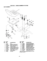
Страница 9: ...inal rminal INSTALL SEAT Adjust seat before tightening adjustment knob Remove cardboard packing on seat pan Place seat on seat pan and assemble shoulder bolt Tighten shoulder bolt securely Assemble adjustment knob and flat washer loosely Do not tighten Lower seat into operating position and sit on seat Slide seat until a comfortable position is reached which allows you to press clutch brake pedal ...

Страница 10: ...tion of this manual INSTALL MULCHER PLATE Install two latch hooks to mulcher plate using screw washer lock washer and weld nut as shown NOTE Pro assemble weld nut to latch hook by inserting weld nut from the top with hook pointing down Tighten hardware securely Raise and hold deflector shield in up right position Place front of mulcber plate over front of mower deck opening and slide into place as...

Страница 11: ...C TION FROM THIS QUALITY PRODUCT Please review the following checklist All assembly instructions have been completed No remaining loose parts in carton Battery is properly prepared and charged Minimum 1 hour at 6 amps Seat is adjusted comfortably and tight ened securely All tires are properly inflated For ship ping purposes the tires were overinflat ed at the factory Be sure mower deck is properly...

Страница 12: ...INE ON ENGINE OFF OIL PRESSURE LIGHTS ON OVER TEMP _ LIGHT FUEL CHOKE MOWER HEIGHT PARKING BRAKE UNLOCKED MOWER LIFT LOCKED r l R N H ATTACHMENT REVERSE NEUTRAL HIGH CLUTCH ENGAGED L 31 LOW PARKING BRAKE KEEP AREA CLEAR SLOPE HAZARDS ATTACHMENT IGNITION CLUTCH DISENGAGED SEE SAFETY RULES SECTION DANGER KEEP HANDS AND FEET AWAY FREE WHEEL Automatic Models only 12 ...

Страница 13: ...NT CLUTCH LEVER Used to engage the mower blades or other attach ments mounted to your tractor LIGHT SWITCH Turns the headlights on and off THROTTLE CHOKE CONTROL Used to control engine speed CLUTCH BRAKE PEDAL Used for declutching and braking the tractor and starting the engine HEIGHT ADJUSTMENT KNOB Used to adjust the mower cutting height GEARSHIFT LEVER Selects the speed and direction of the tra...

Страница 14: ...y Always remove key when leaving tractor to prevent unauthorized use 14 Never use choke to stop engine IMPORTANT Leaving the ignition switch in any position other than OFF will cause the battery to be discharged dead NOTE Under certain conditions when tractor is standing idle with the engine run ning hot engine exhaust gases may cause browning of grass To eliminate this possibility always stop eng...

Страница 15: ...ear Be sure you have allowed room for tractor to roll slightly as you restart movement To restart movement slowly release parking brake and clutch brake pedal Make all turns slowly TO TRANSPORT Raise attachment lift to highest position with attachment lift control When pushing or towing your tractor be sure gearshift lever is in neutral N position Do not push or tow tractor at more than five 5 MPH...

Страница 16: ...on seat in operating position depress clutch brake pedal and set parking brake Place gear shift lever in neutral N posi tion Move attachment clutch to DISEN GAG ED position Move throttle control to choke position NOTE Before starting read the warm and cold starting procedures below Insert key into ignition and turn key clockwise to START position and release key as soon as engine starts Do not run...

Страница 17: ...ting attachments select a ground speed that will suit the terrain and give best performance of the at tachment being used f 1 J MULCHING MOWING TIPS IMPORTANT For best performance keep mower housing free of built up grass and trash Clean after each use The special mulching blade will recut the grass clippings many times and reduce them in size so that as they fall onto the lawn they will disperse ...

Страница 18: ... from the warranty operator must maintain tractor as instructed in this manual Some adjustments will need to be made periodi cally to properly maintain your tractor All adjustments in the Service and Adjustments section of this manual should be checked at least once each season Once a year you should replace the spark plug clean or replace air filter and check blades and belts for wear A new spark...

Страница 19: ...s mower blades must be kept sharp Replace bent or damaged blades BLADE REMOVAL Raise mower to highest position to allow access to blades Remove hex bolt lock washer and flat washer securing blade Install new or rasharpened blade with trailing edge up towards deck as shown 19 IMPORTANT To ensure proper assembly center hole in blade must align with star on mandrel assembly Reassemble hex bolt lock w...

Страница 20: ...y each time you check the oil level TO CHANGE ENGINE OIL Determine temperature range expected before oil change All oil must meet API service classification SF SG or SH Be sure tractor is on level surface Oil will drain more freely when warm Catch oil in a suitable container Remove oil fill cap dipstick Be careful not to allow dirt to enter the engine when changing oil Remove drain plug After oil ...

Страница 21: ...dirty conditions remove the blower housing and other cooling shrouds Clean the cooling fins and external surfaces as necessary Make sure the cooling shrouds are reinstalled NOTE Operating the engine with a blocked grass screen dirty or plugged cooling fins and or cooling shrouds re moved will cause engine damage due to overheating MUFFLER Inspect and replace corroded muffler and spark arrester if ...

Страница 22: ...lutch lever by removing retainer spring Disconnect anti swaybar from chassis bracket by removing retainer spring Disconnect suspension arms from rear deck brackets by removing retainer springs Clutch Lever Clutch Rod_ Suspension Arms Disconnect front links from deck by removing retainer springs Raise lift lever to raise suspension arms Slide mower out from under trac tor IMPORTANT If an attachment...

Страница 23: ...ted so that the front is approximately 1 8 to 1 2 lower than the rear when the mower is in its highest position Check adjustment on right side of tractor Measure distance D directly in front and behind the mandrel at bottom edge of mower housing as shown Before making any necessary adjust ments check that both front links are equal in length Both links should be approximately 10 3 8 If links are n...

Страница 24: ...nce there is a belt installation guide decal on bottom side of left footrest Remove mower See TO REMOVE MOWER in this section of this manual Remove belt from stationary idler and clutching idler Pull belt slack toward rear of tractor Remove belt upwards from transaxle pulley by deflecting belt keepers Pull belt toward front of tractor and remove downwards from around engine pulley Install new belt...

Страница 25: ... and battery Positive Terminal Negative Terminal TO REMOVE CABLES REVERSE ORDER BLACK cable first from chassis and then from the fully charged battery RED cable last from both batteries REPLACING BATTERY ACAUTION Do not short battery ter minals by allowing a wrench or any other object to contact both terminals at the same time Before connecting battery remove metal bracelets wrist watch bands ring...

Страница 26: ... air mixture urning the adjusting needles out ounterclockwise increases the supply of Jel to the engine giving a richer fuel air _ixture IMPORTANT Damage to the needles and the seats in carburetor may result if nee dle is turned in too tight NOTE The carburetor on this engine is low emission It is equipped with an idle fuel adjusting needle with a limiter cap which allows some adjustment within th...

Страница 27: ...from tractor for storage do not store battery directly on concrete or damp surfaces ENGINE FUEL SYSTEM IMPORTANT It is important to prevent gum deposits from forming in essential fuel system parts such as carburetor fuel filter fuel hose or tank during storage Also experience indicates that alcohol blended fuels called gasohol or using ethanol or methanol can attract moisture which leads to separa...

Страница 28: ... Corroded battery termi nals Fill fueltank See TO STAR T ENGINE in Operation section Wait several minutes before attempting to start Replace spark plug Clean replace air filter Replace fuel filter Drain fuel tank and carbure tor refill tank with fresh gasoline and replace fuel fil ter Check all wiring See To Adjust Carburetor in Service and Adjustments section Contact an authorized ser vice center...

Страница 29: ...rom buildup of Excessive vibration Engine continues to run when opera tor leaves seat with attachment clutch engaged Poor cut uneven Set in Higher Cut posi tion reduce speed Adjust throttle control Clean underside of mower housing Clean replace air filter Check oil level change oil Clean and regap or_change spark plug Replace fuel filter Drain fuel tank and refill with fresh gasoline Drain fuel ta...

Страница 30: ... out Faulty light switch Loose or damaged wiring Blown fuse Bad battery cell s Poor cable connections Faulty regulator if so equipped Faulty alternator Engine throttle control not set at SLOW position for 30 seconds before stopping engine Replace mower drive belt Replace idler pulley Replace blade mandrel Place throttle control in FAST position Shift to slower speed Allow grass to dry before mowin...

Страница 31: ...D AMMETER OPTIONAL w_ E BL_J _ SPARK IGNITION PLUG UNIT GAP 2 PLUGS ON TWIN CYL ENGINES CHA_ING SYSTEM IITPUT I SAMP I_ II 3_0 RPM REGULATOR I OPERATOR PRESENCE RELAY 3 85 86 STATOR BRAKE IGNITION SWITCH HEADLIGHTS _CK RE0 NON REMOVABLE REMOVABLE CONNECTIONS CONNECTIONS WIRING INSULATED CLIPS POSITION CIRCUIT MAKE OFF G M L NONE RUN_I IGHT B L A Y RUN B L NONE START S L S NONE NOTE IF WIRING INSUL...

Страница 32: ...ELECTRICAL TRACTOR MODEL NUMBER 917 271090 41 33 25 i i 32 ...

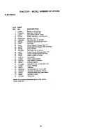
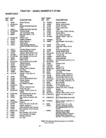
Страница 33: ...y Mech Hinge Switch Intadock N OPN N OPN Washer Lock 1 4 Nut Hex Jam 1 4 20 UNC Hamess LightSocket w 4152J LightBulb Cable Battery 6 Gauge Red 11 Cable Battery 6 Gauge Red W16 Wire Fuse 30Amp Nut Keps Hex 1 4 20 Unc Cable Ground 6 Gauge Black 12 Switch Plunger Normal OP Olive Switch Ignition 4 Position Nut Ignition Cover Ignition Switch Key Molded Craftsman Harness Ignition Bolt BIk Fin Hex 1 4 20...

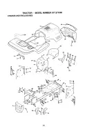
Страница 34: ...TRACTOR MODEL NUMBER 917 271090 CHASSIS AND ENCLOSURES 58 28 31 _1116 3 2 i 4 ...

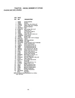
Страница 35: ...ash Dash Bolt Carriage 3 8 16 x 3 4 Panel Dash LH Clip nnnermanGdlle P L Panel Dash RH Screw Thd Roll 3 8 16 x 1 2 HoodAssembly Bumber Hood Washer 13 32 x 13 16 x 12 Gauge Locknut Grillew ClipsMS 558 Lens Grille Fender FootrestPnt STLT N Hold 558 Bracket Fender Suppert ScrewThdrol 5 16 18x 1i2 PivotBracketAssembly LH PivotBracketAssembly RH Nut Lock w Insert1 4 20 UNC Washer 9 32 x 7 8 x 16 Gauge ...

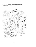
Страница 36: ...TRACTOR MODEL NUMBER 917 271090 GROUND DRIVE 36 ...

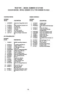
Страница 37: ...165494 Gauge 160 19292016 47 127783 Pulley Idler V Groove Plastic 161 72140406 48 154407 BellcrankClutchGrad DryStl 49 123205X Retainer Belt 162 73680400 50 STD523715 Boil 163 74780416 51 STD541437 NutCrown Lock3 8 16 UNC 164 19091010 52 STD541431 Nut Crown Look5 16 18 UNC 53 105710X Link Clutch t85 165623 55 105709X Spring ClutchReturn 166 166880 56 STD523712 Bolt FinHex 3 8 16 x 1 1 4 168 165492...

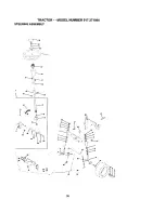
Страница 38: ...TRACTOR MODEL NUMBER 917 271090 STEERING ASSEMBLY _lt _ _ J _ 39 I 2S U 38 ...

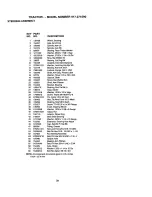
Страница 39: ...Draglink Extended Stamped Washer Lock Hvy Hlcl Spr 3 8 Bearing Axle STLT GT Locknut Flange 5 8 11 UNC Shaft AsmStrg PrivateLabel Washer Thrust 515 x 750 x 033 Support Shaft Screw Hex Wshhd Torx Shaft Asm Pittman Bracket Steering Bushing Rod 13e BIk Lt Gear Sector Washer 13 32 x 7 8 x 16ga Screw Thdrol3 8 16x3 4 Ty tt Pin Cotter 1 8 x 3 4 Cad Rod ReWire Form 19 75 Mech Bushing Strg 5 8 Id Dash Scre...

Страница 40: ... f_p c TOP _ 0_ _U_ EP 9 t7 _ f t ogo _o ...

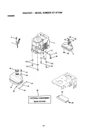
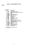
Страница 41: ...gine See Breakdown KohlerModel No CV16s 43520 Muffler Gasket Nipple Pipe3 8 NPT x 3ol 2 Elbow Std 90 Degree3 8 18 Npt Washer Shield BRN DBR Guard Arrestor Spark Tank Fuel Cap Assembly FuelTank Vented Clamp Hose BIk Screw Thdrol5 16o18 x 3 4 TY T Line Fuel PlugOil Drain Order From Engine Manufacturer Bushing Snap Fuel Line Screw Hex Washer Head Thd Roll 1 4 20 x 3 4 Washer 9 32 x 7 8 x 16Gauge Wash...

Страница 42: ...nc 17 123976X 7 124181X SpdngSeatCprsn2250BIkTi 21 153236 8 17490616 Screw Thdrol3 8 16 X 1 Ty tt 22 STD541431 9 19131614 Washer 13 32X 1 X 14Ga 24 19171912 10 155925 PanPntSeat blk 25 127018X 11 166369 KnobSeat BracketPntMounting Switch Bushing Snap BIkNy150 Id BoltRdhdShtNk 1 4 20x1 1 2 SpacerSplit28 X 96 Zinc SpdngCprsnI 27 BIk Pnt NutLock 1 4 Lga FigGr 5 Zinc BoltShoulder5 16 18 Unc 2A NutHex ...

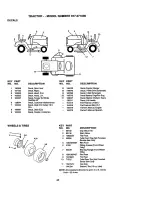
Страница 43: ...r Decal V Belt DriveSchematic Decal V Belt Schematic Decal Battery Dngr PsnEng Decal BatteryDiehard Sears Decal LiftHandle Pad FootrestLH STLT Pad FootrestRH STLT Owner sManual English Owner sManual Spanish WHEELS TIRES 2 _ 5 8 4 10 11 KEY PART NO NO DESCRIPTION 1 59192 Cap Value Tire 2 65139 Stem Value 3 106222X Tire Fmnt 4 59904 Tube FrontTire Not Providsd Service Item Only 5 106732X427 Rim Fron...

Страница 44: ...TRACTOR MODEL NUMBER 917 271090 LIFT ASSEMBLY 49 5 12 3O 3 26 8 I I 13 31 32 13 19 2O 2O 15 44 ...

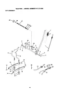
Страница 45: ...3350800 NutJam Hex 1 2 13 Unc 17 130171 TrunnionBIk Zinc 18 73800800 LockNut Hex with Washer Insert 1 2 13 UNC 19 139868 Arm SuspensionRear 20 STD624008 RetainerSpring 23 110807X Nut Special 24 19131016 Washer 13 32 x 5 8 x 16Ga 25 2876H Spring2 118 26 76020308 Pin Cotter 3 32 x 1 2 27 126971X RedAdjustLift Zinc 7 49 Wrk 28 73350600 Nut Hex Jam 3 8 16unc 29 138057 Knob Inf 3 8 16unc BIk W Syn 30 1...

Страница 46: ...TRACTOR MODEL NUMBER 917 271090 MOWER DECK 76 113 111 114 118 _t 5 6 21 _ i_ 121 114 46 ...

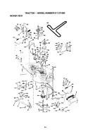
Страница 47: ...7 36 131494 Pulley Idler Flat 121 143723 37 STD551037 Washer 13 32 x 13 16x 16 128 153390 Gauge 129 19131312 40 STD541437 Nut Crownlock3 8 16 UNC 130 STD523710 41 133551 Rod Pivot with Nibs 43 140083 Rod Clutch Secondary with 131 STD533710 Nibs 44 140088 Guard Mandrel L H 132 19132203 45 STD624003 Retainer 46 137729 Screw Thd Roll 1 4 20 x 5 8 141 6266H 48 133944 Washer Hardened 130794 49 155066 R...

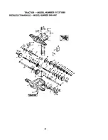
Страница 48: ...TRACTOR MODEL NUMBER 917 271090 PEERLESS TRANSAXLE MODEL NUMBER 206 545C 8 48 ...

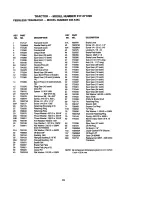
Страница 49: ...x 031W 77 788078A 29A 780160 Thrust Washer 762 ID x 031W 79 792144 29B 780051 Thrust Washer 762 ID x 031W 82 778333 29C 780199 Anti Rotation Washer 632 30 780108 Cup Washer 1 127 ID x 032W 83 778338 31 780001 Rat Washer 750 ID x 056W 85 792154 Use ASNeeded 87 788089A 31A 780195 Rat Washer 750 ID x 062W 150 788093A 32 788083 Oil Seal 5 8 157 788088A 34 780194 Bushing 563 180 730229A 35 780193 Range...

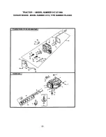
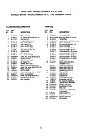
Страница 50: ...TRACTOR MODEL NUMBER 917 271090 KOHLER ENGINE MODEL NUMBER CV16 TYPE NUMBER PS 43520 CYUNDER HEAD VALVE AND EIREATHERJ 14 10 18 _ t4 5O ...

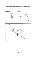
Страница 51: ...eather reed Reed breather DESCRIPTION 1 2 3 4 5 6 7 8 9 10 11 12 13 14 15 16 17 18 19 21 22 23 24 12 032 0_3 Seal crankshaft Block cylinder Use ShortBlock 12 522 18 12 445 02 M 0839025 12 380 17 12 758 49 12 089 31 12 422 08 12 422 09 12 422o10 12 422 11 12 422 12 12 422 13 12 422 07 12 144 27 12 874 07 24 874 11 12 874 08 _2 874 09 12 01802 12 10807 12 108 08 12 108 09 12 067 05 12 067 06 12 380 ...

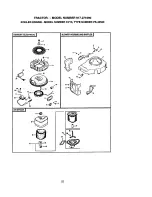
Страница 52: ...TRACTOR MODEL NUMBER 917 271090 KOHLER ENGINE MODEL NUMBER CV16 TYPE NUMBER PS 43520 IGNITION ELECTRICAL I 22 _ 2 10 AIR INTAKE I t 8 BLOWER HOUSINGAND BAFFLES I 13 4 L 52 ...

Страница 53: ...or assembly 15amp Spark Plug 12 12 063 08 Clip cable 13 12 063 09 Screw hex flange M5x0 8xl 0 NOT ILLUSTRATED 2 X 25 92 Module ignition T_n ninal Screw hex socketM5x0 8x20 AIR INTAKE FILTRATION 2 Screw pan head M4 2xl 3 2 KEY PART Module speed advance NO NO Shoulder M6X1 0X16 4 Lead Lead Hamess Washer plain 5 16 Connector ClipCable Screw hex flangeM5xO 8xl0 8 Washer plain 1 4 Plate blower housing ...

Страница 54: ...TRACTOR MODEL NUMBER 917 271090 KOHLER ENGINE MODEL NUMBER CV16 TYPE NUMBER PS 43520 STARTING SYSTEM J 3m o O 8 ENGINE CONTROLS I OIL PAN I LUBRICATION I _ 13 t I _ 22 7__ I 111 _ 19 0_16 54 ...

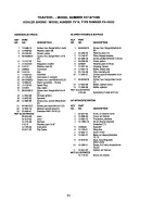
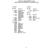
Страница 55: ...ng oil fill cap O Ring upperoilfilltube Tube oil fill Screw hox flange M5xO 8x20 O Ring loweroil filltube Screen oil pickup Cover oil pickupscreen Screw bex flange M5xO 8x16 Valve oil pressure relief Rlter oil Plug sq hd solid3 8 Pump oilassembly O Ring oil pump cover Cover oil pump Screw hex flange M5xO 8x16 3 Seal oil P T O end Screw hex flange M8xl 25x45 11 Screw hex flange M8x1 25x45 Assembly ...

Страница 56: ...TRACTOR MODEL NUMBER 917 271090 KOHLER ENGINE MODEL NUMBER CV16 TYPE NUMBER PS 43520 CRANKSHAFT I 11 3m_ FUEL SYSTEM I 17 t 56 ...

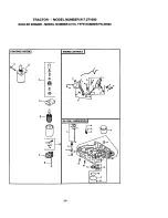
Страница 57: ...s6 7 8 qty 1 12 454 01 25452 20 Gasket air cleaner Carburetorassembly For informationonlynot available separately Gasket carburetor 2 Deflector heat Clipcable Clamp hose 2 Une fuel9 Riter fuel Kit float Kit carburetorrepair Gasket carburetor Gasket air cleaner Gasket howl Gasket bowl screw Seal solenoid Kit solenoidrepair Gasket howl screw Re wire Terminal Re cable Screw thread forming M5XO SXIO S...

Страница 58: ...58 ...
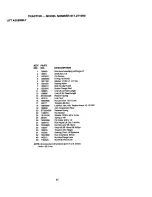
Страница 59: ... ONLY RIDE UP AND DOWN HILL NOT ACROSS HILL ol O I h Operate your Tractor up and down the face of slopes not I I greater than 15 never across the face Make turns gradu I ally to prevent tipping or loss of control Exercise extreme caution when changing direction on slopes ...

Страница 60: ...icio de reparaci6n a domicilio 1 800 676 5811 For the location of a Sears Parts and Repair Center in your area Call 24 hours a day 7 days a week 1 800 488 1222 For information on purchasing a Sears Maintenance Agreement or to inquire about an existing Agreement Call 9 am 5 pm Monday Saturday 1 800 827 6655 When requesting service or ordering parts always provide the following information Product T...

Отзывы: