background image

Содержание EZ3 917.271014

Страница 1: ...tion Maintenance Repair Parts CAUTION Read and follow all Safety Rules and Instructions before operating this equip ment For answers to your questions about this product Call 1 800 659 5917 Sears Craftsman Help Line 5 am 5 pro Mon Sat Sears Roebuck and Co Hoffman Estates IL 60179 Visit our Craftsman website www sears com craftsman ...

Страница 2: ...te of purchase Please contact your nearest service center After 30 days from the date of purchase warranty service is available by taking your Craftsman riding equipment to your nearest Sears Service Center In home warranty service will still be available after 30 days from the date of purchase but e standard trip charge will apply This warranty applies only while this product is in the United Sta...

Страница 3: ...ly straight down the slope DO NOT Do notturn on slopes unless neces sary and then turn slowly and gradual ly downhill if possible Do not mow near drop offs ditches or embankments The mower could sud denly turn over if a wheel is over the edge of a cliff or ditch or if an edge caves in Do not mow on wet grass Reduced traction could cause sliding Do not try to stabilize the machine by putting your f...

Страница 4: ...n Keep children out of the mowing area and under the watchful care of another responsible adult Be alert and turn machine off if children enter the area Before and when backing look behind and down for small children Mow up and down slopes 15 Max not across Remove obstacles such as rocks tree limbs etc Watch for holes ruts or bumps Un even terrain could overturn the ma chine Tall grass can hide ob...

Страница 5: ...will enable you to assemble and maintain your tractor properly Always observe the SAFETY RULES MAINTENANCE AGREEMENT A Sears Maintenance Agreement is avail able on this product Contact your nearest Sears store for details CUSTOMER RESPONSIBILITIES Read and observe the safety rules Follow a regular schedule in maintain ing caring for and using your tractor Follow the instructions under Mainte nance...

Страница 6: ...Bolt 5 16 18 x 1 1 4 1 Hex Bolt 3 8 16 x 1 1 Lockwasher 3 8 1 Large Flat Washer 1 Locknut 5 16 18 1 Knob 1 Washer 17 32 x 1 3 16 x 12 Gauge 1 Shoulder Bolt 5 16 18 2 Washers 3 16 x 3 4 x 16 Gauge __ 10 x 5 8 2 Weld Nuts 10 2 Lock Washers 10 R ...

Страница 7: ...late F 7 Video Cassette Steering Boot m Manual Slope Sheet ii I I I I I I I I Parts Bag Steering Wheel Parts Bag contents not shown full size Steering Wheel Adapter Steering Extension Shaft _ Sth r_g Insert _1 I i 2 Latch Hook Assemblies 4B 2 Keys 7 ...

Страница 8: ...flat Check for any additional loose parts or boxes and remove BEFORE ROLLING TRACTOR OFF SKID ATTACH STEERING WHEEL ASSEMBLE EXTENSION SHAFT AND BOOT Slide extension shaft onto lower steer ing shaft Align mounting holes in ex tension and lower shafts and install 5 16 hex bolt and Iocknut Tighten se curely IMPORTANT Tighten bolt and nut se curely to 18 22 ft Ibs torque Place tabs of steering boot o...

Страница 9: ...ts highest position Release parking brake by depressing clutch brake pedal Place gearshift lever in neutral N posi tion Roll tractor forward off skid Remove banding holding discharge guard up against tractor TO DRIVE TRACTOR OFFSKID _brWAR NING Before starting read un s ana and follow all instructions in the Operation section of this manual Be sure tractor is in a well ventilated area Be sure the ...

Страница 10: ... hooks to mulcher plate using screw washer lock washer and weld nut as shown NOTE Pre assemble weld nut to latch hook by inserting weld nut from the top with hook pointing down Tighten hardware securely Raise and hold deflector shield in up right position Place front of mulcher plate over front of mower deck opening and slide into place as shown Hook front latch into hole on front of mower deck Ho...

Страница 11: ...at the factory Be sure mower deck is properly leveled side to side front to rear for best cutting results Tires must be properly inflated for leveling Check mower and drive belts Be sure they are routed properly around pulleys and inside all belt keepers Check wiring See that all connections are still secure and wires are properly clamped WHILE LEARNING HOW TO USE YOUR TRACTOR PAY EXTRA AI I ENTIO...

Страница 12: ...ING A ENGINE ON ENGINE OFF OIL PRESSURE OGHTS ON OVER TEMP 1P LIGHT FUEL CHOKE MOWER HEIGHT PARKING BRAKE UNLOCKED MOWER LIFT LOCKED R N H L ATTACHMENT REVERSE NEUTRAL HIGH LOW PARKING BRAKE CLUTCH ENGAGED _ _ KEEP AREA CLEAR SLOPE HAZARDS ATFACHMENT IGNITION CLUTCH DISENGAGED DANGER KEEP HANDS AND FEET AWAY SEE SAFETY RULES SECTION FREE WHEEL Automatic Models only 12 ...

Страница 13: ...stitute ATTACHMENT CLUTCH LEVER Used to engage the mower blades or other at tachments mounted to your tractor LIGHT SWITCH Turns the headlights on and off THRO I rLE CHOKE CONTROL Used to control engine speed CLUTCH BRAKE PEDAL Used for declutching and braking the tractor and starting the engine GEARSHIFT LEVER Selects the speed and direction of the tractor ATTACHMENT LIFT LEVER Used to raise and ...

Страница 14: ...remove key when leav ing tractor to prevent unauthorized use Never use choke to stop engine IMPORTANT Leaving the ignition switch in any position other than OFF will cause the battery to be discharged dead NOTE Under certain conditions when tractor is standing idle with the engine running hot engine exhaust gases may cause browning of grass To eliminate this possibility always stop engine when sto...

Страница 15: ...perator to leave the seat with the engine running and the attachment clutch engaged will shut off the engine Select desired height of cut Start mower blades by engaging attach ment clutch control TO STOP MOWER BLADES disengage attachment clutch control _ CAUTI ON Do notoperatethe mower withouteitherme entiregrasscatcher on mowersso equipped or the dischargeguard in place Attachment Clutch Lever Po...

Страница 16: ...uel next season See Storage Instructions for additional informa tion Never use engine or carburetor cleaner products in the fuel tank or permanent dam age may occur _CAUTION Fillto bottom of gas tank filler neck Do not overfill Wipe off any spilled oil or fuel Do not store spill or use gasoline near an open flame TO START ENGINE When starting the engine for the firsttime or if the engine has run o...

Страница 17: ...t will suitthe terrainand give bestperformance of the attachment being used 1 MULCHING MOWING TIPS IMPORTANT For best performance keep mower housing free of built up grass and trash Clean after each use The special mulching blade will recut the grass clippings many times and reduce them in size so that as they fall onto the lawn they will disperse into the grass and not be noticed Also the mulched...

Страница 18: ...ator abuse or negligence To receive full value from the warranty operator must maintain tractor as instructed in this manual Some adjustments will need to be made periodically to properly maintain your tractor All adjustments in the Service and Adjust ments section of this manual should be checked at least once each season Once a year you should replace the spark plug clean or replace air filter a...

Страница 19: ...sharpened blade with trailing edge up towards deck as shown IMPORTANT To ensure proper assembly center hole in blade must align with star on mandrel assembly Reassemble hex bolt lock washer and flat washer in exact order as shown Tighten bolt securely 27 35 Ft Lbs torque IMPORTANT Blade bolt is grade 8 heat treated Trailing Edge Blade Up Lock Washer Mandre Assembly Grade_ Flat Washer A Grade 8 hea...

Страница 20: ...on level surface Oil will drain more freely when warm Catch oil in a suitable container Remove oil fill cap dipstick Be careful not to allow dirt to enter the engine when changing oil Remove drain plug After oil has drained completely re place oil drain plug and tighten se curely Refill engine with oil through oil fill dip stick tube Pour slowly Do not overfill For approximate capacity see PROD UC...

Страница 21: ... than 100 hours in one year Drain oil from engine crankcase See TO CHANGE ENGINE OIL_ in this sec tion of this manual through step re move drain plug Remove oil filter and wipe off filter adapter Apply a thin coating of new engine oil to the rubber gasket on replacement oil fil ter Install replacement oil filter on filter adapter Turn oil filter clockwise until rubber gasket contacts the filter ad...

Страница 22: ...from clutch lever by removing retainer spring Disconnect anti swaybar from chassis bracket by removing retainer spring Disconnect suspension arms from rear deck brackets by removing retainer springs Disconnect front links from deck by re moving retainer springs Raise lift lever to raise suspension arms Slide mower out from under trac tor IMPORTANT If an attachment other than the mower deck is to b...

Страница 23: ...urns When distance D is 1 8 to 1 2 lower at front than rear tighten nuts F against trunnion on both front links To raise front of mower loosen nut F from trunnion on both front links Tighten nut E on both front links an equal number of turns When distance D is 1 8 to 1 2 lower at front than rear tighten nut F against trunnion on both front links Recheck side to side adjustment _ _ _ _ _ _ Mandrel ...

Страница 24: ...oO_Operating Arm TO REPLACE MOTION DRIVE BELT Park the tractor on level surface Engage parking brake For assistance there is a belt installation guide decal on bottom side of left footrest Remove mower See q O REMOVE MOWER in this section of this manual Remove belt from stationary idler and clutching idler Pull belt slack toward rear of tractor Remove belt upwards from transaxle pulley by deflecti...

Страница 25: ... use your tractor battery to start other vehicles TO ATTACH JUMPER CABLES Connect each end of the RED cable to the POSITIVE terminal of each bat tery taking care not to short against chassis Connect one end of the BLACK cable to the NEGATIVE terminal of fully charged battery Connect the other end of the BLACK cable to good CHASSIS GROUND away from fuel tank and battery TO REMOVE CABLES REVERSE OR ...

Страница 26: ...uthorized engine manufacturer s service outlet TO ADJUST THROTTLE CONTROL CABLE The throttle control has been preset at the factory and adjustment should not be necessary Check adjustment as de scribed below before loosening cable If adjustment is necessary proceed as fol lows With engine not running move throttle control lever from slow to choke posi tion Slowly move lever from choke to fast posi...

Страница 27: ...rottle control lever in slow position turn idle fuel adjustment needle in clockwise until engine begins to die and then turn out counterclockwise until engine runs rough Turn needle to a point midway between those two positions Recheck idle speed Readjust if neces sary ACCELERATION TEST Move throttle control lever from slow to fast position If engine hesitates or dies turn idle fuel adjusting need...

Страница 28: ...l system parts such as carburetor fuel filter fuel hose or tank during storage Also experience indicates that alcohol blended fuels called gasohol or using ethanol or methanol can attract moisture which leads to separation and formation of acids during storage Acidic gas can damage the fuel system of an engine while in storage Drain the fuel tank Start the engine and let it run until the fuel line...

Страница 29: ...ty air filter Low oil level dirty oil CORRECTION Fill fuel tank See TO START ENGINE in Operation section Wait several minutes before at tempting to start Replace spark plug Clean replace air filter Replace fuel filter Drain fuel tank and carburetor refilltank with fresh gasoline and replace fuel filter Check all wiring See To Adjust Carburetor in Service and Adjustments section Contact an authoriz...

Страница 30: ...t grass Mower deck not level Low uneven tire air pressure Worn bent or loose blade CORRECTION Clean and regap or change spark plug Replace fuel filter Drain fuel tank and refillwith fresh gasoline Drain fuel tank and carburetor refilltank with fresh gasoline and replace fuel filter Connect and tighten spark plug wire Clean engine air screen fins Clean replace muffler Check all wiring See To Adjust...

Страница 31: ...r cable connections Faulty regulator if so equipped Faulty alternator Clean underside of mower hous ing Replace mower drive belt Reinstall blades sharp edge down Replace with blades listed in this manual Clean around mandrels to open vent holes Turn switch ON Replace bulb s Check replace light switch Check wiring and connections Replace fuse Replace battery Check clean all connections Replace regu...

Страница 32: ...32 ...

Страница 33: ...UGHT1NG S_ JTEM L I G NITION SWITCH POSITION I CIRCUIT MAKE OFF I G M L NONE RUN LIGHT B L A Y RUN B L NONE START B L S NONE NOTE YOUR TRACTOR IS EQUIPPED WITH A SPECIAL ALTERNATOR SYSTEM THE UGHTS ARE NOT CONNECTED TO THE BATTERY BUT HAVE THEIR OWN ELECTRICAL SOURCE BECAUSE OF THIS THE BRIGHTNESS OF THE LIGHTS WILL CHANGE WITH ENGINE SPEED AT IDLE THE LIGHTS WtLL DIM AS THE ENGINE IS SPEEDED UP T...

Страница 34: ...ELECTRICAL TRACTOR MODEL NUMBER 917 271014 I I 24 41 I I 34 ...

Страница 35: ...ge Switch Interlock N OPN N CPN Washer Lock 1 4 Nut Hex Jam 1 4 20 UNC Harness Light Socket w 4152J Light Bulb Cable Battery 6 Gauge Red 11 Cable Battery 6 Gauge Red W16 Wire Fuse 15Amp Nut Keps Hex 1 4 20 UNC Cable Ground 6 Gauge BLack 2 Switch Plunger Normal OP Clive Switch Ignition 4 Position Nut Ignition Cover Ignition Switch Key Molded Craftsman Harness Ignition Bolt BIk Fin Hex 1 4 20 UNC x ...

Страница 36: ...TRACTOR MODEL NUMBER 917 271014 CHASSIS AND ENCLOSURES 28 58 12 36 ...

Страница 37: ...Dash Bolt Carriage 3 8 16 x 3 4 Panel Dash LH Clip Tinnerman Grille P L Panel Dash RH Screw Thd Roll 3 8 16 x 1 2 Hood Assembly Bumper Hood Washer 13 32 x 13 16 x 12Gauge Locknut GdlLew ClipsMS 558 Lens Grille FendedFootrest Pnt STLT N Held 558 Bracket Fender Support Screw Thdrol 5 t6 18 x 1 2 Pivot Bracket Assembly LH Pivot BracketAssembly RH Nut Lock w Insert 1 4 20 UNC Washer 9 32 x 7 8 x 16 Ga...

Страница 38: ...TRACTOR MODEL NUMBER 917 271014 GROUND DRIVE 57 62 80 o 113 P 85 3 51 156 1 _ A 30 6 g 37 116 25 I 26 27 38 ...

Страница 39: ...16 x 12 Gauge 158 165589 127783 Pulley Idler V Groove Plastic 159 165494 154407 BellcrankClutchGrnd Dry Stl 160 19_920 6 123_05X Retainer Belt 161 72140406 _715 Bolt 1 To41437 NutCrownLock3 8 16 UNC 162 73680400 STD541431 NutCrownLock5 16 18 UNC 163 74780416 105710X Link Clutch 105709X Spring ClutchReturn 164 19091010 STD523712 BoltFinHex 3 6 16x1 1 4 166 166880 130801 V Belt GroundDrive 168 1654 ...

Страница 40: ...TRACTOR MODEL NUMBER 917 271014 STEERING ASSEMBLY 11 13 39 _ J _ 1 41 _ 42 44 4O ...

Страница 41: ...k Draglink Extended Stamped Washer Lock Hvy Hlcl Spr 3 8 Bearing Axle STLT GT Locknut Flange 5 8 11 UNC Shaft Asm Strg Private Label Washer Thrust 515 x 750 x 033 Support Shaft Screw Hex Wshhd Torx Shaft Asm Pittman Bracket Steering Bushing Rod Tie BIk Lt Gear Sector Washer 13 32 x 7 8 x 16ga Screw Thdrol 3 8 16x3 4 Ty tt Pin Cotter 1 8 x 3 4 Cad Rod Tie Wire Form 19 75 Mech Bushing Strg 5 8 Id Da...

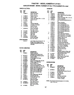
Страница 42: ...ENGINE TRACTOR MODEL NUMBER 917 271014 2 80 29 OPTIONAL EQUIPMENT I Spark Arrester I _ _ _ _e _ I p_ _ _ _ I 23 42 ...

Страница 43: ...eakdown Kohler Model CV15S 41567 Muffler Gasket Kohler CV13 CV16 5 Nipple Pipe 3 8 NPT x 3 1 2 Elbow Std 90 Degree3 6 18 Npt Washer Shield BRN DBR Guard Arrestor Spark Tank Fuel Cap Assembly Fuel Tank Vented Clamp Hose B k Screw Thdrol 5 16 18 x 3 4 TYT Line Fuel PlugOil Drain See Engine Breakdown Bushing Snap Fuai Line Screw Hex Washer Head Thd RoU 1 4 20 x 3 4 Washer 9 32 x 7 8 x 16 Gauge Washer...

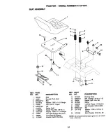
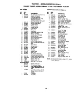
Страница 44: ... 32 x 1 x 10 Gauge 16 121250X Clip Push In Hinged 17 123976X Nut 21 153236 SDring Seat 22 ST To41431 Screw Thd Roll 3 8 16 x 1 24 19171912 Washer f3 3 2 x fx 14 Gauge Pan Seat EmbossQCK Conn 25 t27018X KnobSeat AdjWingnut Bracket Switch Mounting Bushing Snap Bolt Cardage 1 4 20 x 1 1 2 Spacer Split 28 x 96 sprig Locknut Flange 1 4 Grade Bolt Shoulder 5 16 t8 UNC Nut Washer 17 32 x 1 3 16 x 12 Gaug...

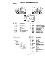
Страница 45: ...lt DriveSchematic Decal Fend Sd Wht Rad 6sp Decal V BeltSchematic Decal BatteryDngdPsn Eng Decal Battery Diehard Sears Decal LiftHandle Pad FootrestLH STLT Pad FootrestRH STLT Owners Manual English Owners ManuaJ Spanish WHEELS TIRES 4 10 11 KEY PART NO NO DESCRIPTION 1 59192 ValveCap 1ire 2 65139 Stem Valve 3 106222 13re Front 4 59904 Tube FrontTire NotProvided Service Item Only 5 106732X427 Rim F...

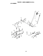
Страница 46: ...TRACTOR MODEL NUMBER 917 271014 LIFT ASSEMBLY 7 5 2 6 t i i J 20 15 20 16 ...

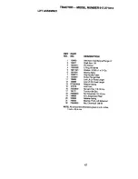
Страница 47: ...ip Handle Ruted 8 122 365X ButtonPlunger Red 11 139865 LinkLiftLh Fixed Length 12 139866 Link Lift Rh Fixed Length 13 S rO6240 _ RetainerSpring 15 127218 Unk Front 16 733 50800 NutJamHex 1_ 3Unc 17 130171 Trunnion BIk Zinc 18 73680800 Nut Crownlock1 2 13Unc 19 13_868 Arm SuspensionRear 20 163552 RetainerSpring 31 140302 Bearing Pivot Uft Spherical 32 73540600 Nut Crownlock 3 8 24 NOTE All componen...

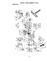
Страница 48: ...MOWER DECK TRACTOR MODEL NUMBER 917 271014 76 17 36 5 116 113 111 11_ 118 4 6 21 16 13 10_ 9_ 21 22 29 28 27 z_ ...

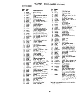
Страница 49: ... Hinge 115 72110504 Screw Thdrol Washer Heed 116 4898H Wesher Spacer 117 165746 Pulley Mandrel 118 73930600 Not Toplock Flanged 119 STD5510_37 Bolt 121 143723 Fastner Christmas Tree 128 153 390 Pulley Idler Flat 129 19131312 Washer 13 32 x 13 16 x 16 Ga 130 STD523710 Not Crownlack 3 8 16 UNC Red Pivot with Nibs 131 S T_710 Rod Clutch Secondary w Nibs Guard Mandrel LH 132 19132203 Retainer Screw Th...

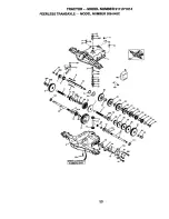
Страница 50: ...TRACTOR MODEL NUMBER 917 271014 _EERLESS TRANSAXLE MODEL NUMBER 206 545C 35A 157 8 7O 6A 1 83 11 47 13 34 29 36 157 45 42A NUMBERS HERE 5O ...

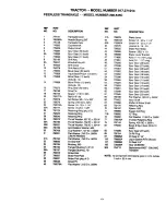
Страница 51: ... 18 786102 Spacer 1 130 X 695 61 778345 Spur Gear 25 teeth 20 792077A Ball 5 16 dia 65 780189 Flat Washer 563 ID x 062W 21 792078 Set Screw 3 8 16 x 3 8 66 776422 Input Shaft 22 792079 Spring 310 OD x 625 L 67 776396 Shifter Brake Shaft 25 792073A Screw 1 4 20 x 1 1 4 69 792170 Retaining Ring 25A 792177 Screw 1 4 20 x 1 3 8 70 786187 Spacer 890 26 792125 Retaining Ring pkg of 2 71 788069 Square Cu...

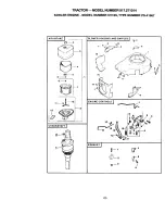
Страница 52: ...CTOR MODEL NUMBER 917 271014 KOHLER ENGINE MODEL NUMBER CV15S TYPE NUMBER PS 41567 AIR INTAKE I _ 5 6 a 11 ___ 10 g CRANKSHAFT I BLOWER HOUSING AND BAFFLES J _4 15 1 ENGINE CONTROLS J EXHAUST _ 1 _ 4 6 8 3 ...

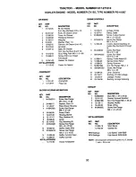
Страница 53: ... 063 05 Baffle Intake Side 13 M 0645016 Screw He Flange M6x 1 0x 16 2 14 12 _ Baffle Cylinder Head 15 12 O63 01 Baffle Cylinder NOTILUJSll IA ED 12 113 64 Decar Horsepower ENGINECONTROLS KEY PART NO NO DESCRIPTION 1 t 2_79 07 Linkage Choke 2 12_237 01 Clamp Cable 3 M_o64020 Screw Locked Socket M6 x 1 0 x 20 2 4 M 0545016 Screw Hex Flange M5 x 8 x 16 5 12o536 09 Control Speed Assembly in cludesKey ...

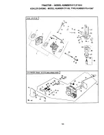
Страница 54: ...TRACTOR MODEL NUMBER 917 271014 KOHLER ENGINE MODEL NUMBER CV15S TYPE NUMBER PS 41567 FUEL SYSTEM j 1o 6 CYLINDER HEAD VALVE AND BREATHER I 25 ...

Страница 55: ...5 12 089 09 Spring Idle Fuel 14 XA26 9 Clamp Hose 2 16 12 086 04 Screw Idle Speed Adjust 15 12 326 03 Hose Breether 17 12_ 89 09 Spring Idle Speed 16 M 0645020 Screw Hex Flange 18 12 146 0_ Plate Throttle M6 x 1 0 x 20 5 19 25086 27 Screw Throttle Rate 2 17 12 0_o 07 Cover ValvewithNipple 20 12 144 09 Shaft Throttle with Lever and 18 235011 Retainer Spring Seal 19 24 032 05 Seal Vah_eStem 21 12 14...

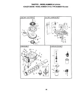
Страница 56: ...TRACTOR MODEL NUMBER 917 271014 KOHLER ENGINE MODEL NUMBER CV15S TYPE NUMBER PS 41567 IGNITION I ELECTRICAL 9 Q 2 OIL PAN LUBRICATION I CRANKCASEJ 23 19 STARTING SYSTEM J o o 56 ...

Страница 57: ...16 M 4_810 5 17 12 144 _ 18 52 139 09 19 12 755484 _ly 20 12 144 24 Includes Key Numbers 2 3 21 X 25 1 _ teat OilFdlCap Includes Key 3 22 12082 01 _ Oips_ m Slvl43681015 O Ring _ Oil F Tube 24 12 154 05 Tube Oi RI Soew I k_ Flange M5x 0 8x 20 O Ring _ Oil F ClTube b _I_R11NG SYb 1131 Screen Oil Pick up _ Oi_Pick up Screen KEY Screw I lex RangeM5x 0 8x 16 NO NO Scre_ HexF_ M10xl Sx25 1 M 0B39070 _ ...

Страница 58: ...58 ...
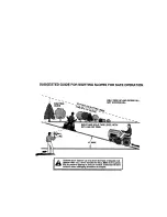
Страница 59: ...ONLY RIDE UP AND DOWN HILL NOT ACROSS HILL _ Operate your Tractor up and down the face of slopes not I I greater than 15 never acro_ s the face Make turns gradu I _1_ ally to prevent tipping or loss of control Exercise extreme J caution when changing direction on slopes I I ...

Страница 60: ...ir or replacement parts you need Call 6 am 11 pm CST 7 days a week PartsDirect SM 1 800 366 PART 1 800 366 7278 Para ordenar piezas con entrega a domicilio 1 800 659 7084 For the location of a Sears Parts and Repair Center in your area Call 24 hours a day 7 days a week 1 800 488 1222 For information on purchasing a Sears Maintenance Agreement or to inquire about an existing Agreement Call 9 am 5 p...

Отзывы: